Configuration options, Configuration options -4, Figure 3-2 – Verilink QUAD DATA (880-503319-001) Product Manual User Manual
Page 28
Configuration
3-4
Verilink QUAD DATA User Manual
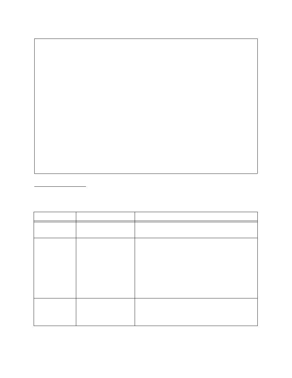
Figure 3-2 QUAD DATA Configuration Menu
Configuration
Options
The options available on the QUAD DATA Configuration Menu are
listed in
Table 3-3
QUAD DATA Configuration Options
-- QUAD DATA CONFIGURATION MENU --
-- QUAD DATA CONFIGURATION MENU --
-- QUAD DATA CONFIGURATION MENU --
-- QUAD DATA CONFIGURATION MENU --
Port 1 Port 2 Port 3 Port 4
Port 1 Port 2 Port 3 Port 4
Port 1 Port 2 Port 3 Port 4
Port 1 Port 2 Port 3 Port 4
In) in service yes yes yes yes
In) in service yes yes yes yes
In) in service yes yes yes yes
In) in service yes yes yes yes
Fn) interface type EIA-530 RS-449 RS-449 V.35
Fn) interface type EIA-530 RS-449 RS-449 V.35
Fn) interface type EIA-530 RS-449 RS-449 V.35
Fn) interface type EIA-530 RS-449 RS-449 V.35
Mn) data port mode DCE DTE DTE DCE
Mn) data port mode DCE DTE DTE DCE
Mn) data port mode DCE DTE DTE DCE
Mn) data port mode DCE DTE DTE DCE
Cn) clock option ST --- --- Invert ST
Cn) clock option ST --- --- Invert ST
Cn) clock option ST --- --- Invert ST
Cn) clock option ST --- --- Invert ST
On) enable LOS detect no no no no
On) enable LOS detect no no no no
On) enable LOS detect no no no no
On) enable LOS detect no no no no
An) remote loopback no no no no
An) remote loopback no no no no
An) remote loopback no no no no
An) remote loopback no no no no
Ln) X.21 C/I setting --- --- --- ---
Ln) X.21 C/I setting --- --- --- ---
Ln) X.21 C/I setting --- --- --- ---
Ln) X.21 C/I setting --- --- --- ---
SRn) DTR/DSR setting DSR/normal DTR/normal DTR/normal DSR/normal
SRn) DTR/DSR setting DSR/normal DTR/normal DTR/normal DSR/normal
SRn) DTR/DSR setting DSR/normal DTR/normal DTR/normal DSR/normal
SRn) DTR/DSR setting DSR/normal DTR/normal DTR/normal DSR/normal
SSn) RTS/CTS setting CTS/normal RTS/normal RTS/normal CTS/normal
SSn) RTS/CTS setting CTS/normal RTS/normal RTS/normal CTS/normal
SSn) RTS/CTS setting CTS/normal RTS/normal RTS/normal CTS/normal
SSn) RTS/CTS setting CTS/normal RTS/normal RTS/normal CTS/normal
SDn) DCD/LL setting DCD/normal LL /off LL /off DCD/normal
SDn) DCD/LL setting DCD/normal LL /off LL /off DCD/normal
SDn) DCD/LL setting DCD/normal LL /off LL /off DCD/normal
SDn) DCD/LL setting DCD/normal LL /off LL /off DCD/normal
SMn) TM/RL setting TM /off RL /off RL /off TM /off
SMn) TM/RL setting TM /off RL /off RL /off TM /off
SMn) TM/RL setting TM /off RL /off RL /off TM /off
SMn) TM/RL setting TM /off RL /off RL /off TM /off
C) copy port T) timing
C) copy port T) timing
C) copy port T) timing
C) copy port T) timing
X) exit this menu
X) exit this menu
X) exit this menu
X) exit this menu
A [0.0.0.2] [1,2] QUAD DATA >
A [0.0.0.2] [1,2] QUAD DATA >
A [0.0.0.2] [1,2] QUAD DATA >
A [0.0.0.2] [1,2] QUAD DATA >
Menu Option
Description
Instructions
In) in service
Places ports in or out of
service.
Place ports in service before building circuits to them.
Type “I1” to place port 1 in service, “I2” for port 2, etc.
Fn) interface type Selects the synchronous
serial interface type for the
port.
The selections for
interface type and data
port mode determine the
adapter (pigtail) cable
required as described to
the right.
Type “F1” through “F4” and choose from:
1)V.35—Use adapter cable 458-501594-001 in DCE mode
or 458-501594-101 in DTE mode.
2)X.21—Use adapter cable 458-502047-001 in DCE mode
DTE mode is not supported for X.21.
3)RS-449—Use adapter cable 458-502059-001 in DCE
mode or 458-502059-101 in DTE mode.
4)EIA-530—Use adapter cable 458-502045-001 in DCE
mode or 458-502045-101 in DTE mode.
Mn) data port
mode
Selects the mode in which
the port operates, DCE or
DTE.
DCE mode is used most often. When connecting the
QUAD DATA port to a DCE device, if DTE mode is used,
that DCE must be configured as the transmit clock source
for the entire shelf. Often it will not be desirable to have a
data port clock the shelf. See “
” in this chapter.