Rear module, Rear module -4 – Verilink QUAD DATA (880-503319-001) Product Manual User Manual
Page 12
Overview
1-4
Verilink QUAD DATA User Manual
Normal Operation
The meaning of the various states is listed in
Table 1-1 LED States
Local Port
The
LOCAL
port on the front of the QUAD DATA module is normally
not used. Configuration and maintenance of the QUAD DATA
module should be done by connecting to the
LOCAL
port of the
associated SCM 3000 controller module.
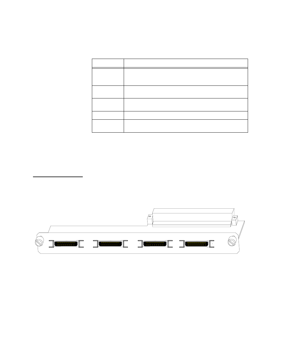
Rear Module
The rear connector module used with the QUAD DATA front module
is a DIM 3030 (DIM stands for Data Interface Module). See
Figure 1-2 DIM 3030 Rear Connector Module
Adapter Cables
The DIM 3030 rear connector module presents 4 mini D-Sub 26-pin
connectors for the data ports. Depending on which electrical
interface type and data port mode is selected in the QUAD DATA
Configuration Menu, an appropriate adapter cable must be used.
The adapter cables all have a mini D-Sub 26-pin connector at one
end and the typical connector for the selected electrical interface at
the other end.
If the data port mode is DCE, use one of the adapter cables in
State
Meaning
Not Lit
The port is not in service. Use the QUAD DATA
Configuration Menu (
) to place the port in
service. If no LEDs are lit, the module has no power.
Solid Green
Normal operation. There are no alarms, no loopbacks, and
the port is in service.
Solid Red
Loss of Signal detection is enabled and the port detects that
DTR is not asserted.
Solid Amber
A Data Port Loopback is active on the port.
Blinking
Amber to Red
The QUAD DATA module is sending a test pattern and
receiving errors.
DATA PORT 1
DATA PORT 2
DATA PORT 3
DATA PORT 4
DIM
3030