Tubetrace, Tubing bundle field test procedure – Thermon TubeTrace Tubing Bundles User Manual
Page 7
TubeTrace
®
Tubing Bundle Field Test Procedure
1. Verify that bundle is properly secured to the support structure without causing deformation to insulation and outer jacket.
2. Thoroughly inspect the TubeTrace tubing bundle to ensure all bends are free of kinks and wrinkles and that fl attening has
not occurred. Refer to the Bending Procedures.
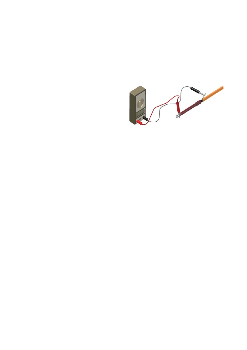
3. Visually inspect bundle for any damage incurred during shipment. Tubing bundle with electric heat trace should be tested to
ensure electrical integrity with at least a 500 Vdc megohmmeter (megger) between the heat trace bus wires and the metallic
braid. IEEE 515 recommends that the test voltage for polymer insulated heat trace be 2500 Vdc and 1000 Vdc for MI.
Minimum resistance should be 20 megohms. (Record 1 on Field Test Report.)
A. Connect the positive lead of the megger to the bus wires.
B. Connect the negative lead of the megger to the metallic
braid.
C. Energize the megger and record the reading. Readings
between 20 megohms and infi nity are acceptable. Readings
below 20 megohms may mean the electrical insulation has
been damaged on polymer insulated heat trace. Recheck the
heat trace for physical damage between the braid and the
heating element; small cuts or scuffmarks on the outer jacket will not affect the megger reading unless there was actual
penetration through the braid and dielectric insulation jacket.
4. Clean the tubing before connection. After all connections have been completed, test the circuit for leaks by subjecting to
pressure equal to or greater than which is to be used in the system, or preferably with suitable hydrostatic tests. Repair any
steam and/or process leaks and retest the system.
5. Properly terminate all heat tracers with appropriate heat trace termination kit.
6. Once the installation is complete, recheck the heat trace with at least a 500 Vdc megohmmeter (megger) between the heat
trace bus wires and the metallic braid as outlined above. IEEE 515 recommends that the test voltage for polymer insulated
heat trace be 2500 Vdc and 1000 Vdc for MI. Minimum resistance should be 20 megohms. (Record 2 on Field Test
Report.)
7. Properly terminate and seal all open ends of each bundle using the appropriate FAK Bundle Accessory Kit.
8. After the power connection is completed, record the panel location and circuit breaker information. Ensure all junction
boxes, temperature controllers, cable glands, etc. are properly secured. Set the temperature controller (if applicable) to
the manual setting and apply rated voltage to the heat tracing circuit(s) for 5 minutes. Record the ambient temperature,
measure and record the circuit(s) voltage at the heat trace connection and electrical current. (Record 3 on Field Test
Report.)
NOTE: To ensure the warranty is maintained through the life of the installation, the testing outlined
on this sheet must be completed on the installed heat trace, and the test results recorded
and sent to [email protected].
6