Tubetrace, Tubing bundles, Installation procedures – Thermon TubeTrace Tubing Bundles User Manual
Page 2
1
Receiving, Storing and Handling . . .
1. Inspect materials for damage incurred during shipping.
Report damages to carrier for settlement.
2. Identify the TubeTrace tubing bundle type to ensure the
proper material and quantity has been received. Boxes
and reels are marked on the outside with part number,
length, product description, weight and customer
purchase order number. Compare information on box or
reel with packing slip and purchase order to verify receipt
of correct shipment.
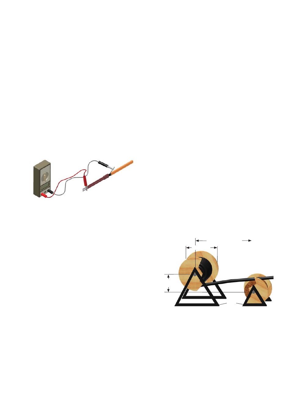
3. The heating cable should be tested to ensure electrical
integrity with at least a 500 Vdc megohmmeter (megger)
between the heating cable bus wires and the heating
cable metallic braid. IEEE 515 recommends that the test
voltage for polymer insulated heating cables be 2500 Vdc.
Minimum resistance should be 20 megohms. (Record 1
on Field Test Report)
TubeTrace
®
Tubing Bundle Layout . . .
1. Determine lengths and number of fi ttings prior to
uncoiling TubeTrace tubing bundle since repeated
uncoiling and re-coiling may “work harden” the tubing or
damage the bundle.
2. Position reel such that TubeTrace tubing bundle may be
pulled from the reel toward the least accessible end point
allowing installation to begin at the end-point working
back toward the reel.
3. To uncoil and straighten TubeTrace tubing bundles anchor
the loose end of the tubing on a fl at surface and roll the
hand coil or shipping reel. If additional straightening is
needed, apply moderate tension to the tubing bundles.
4. Wooden spools of TubeTrace tubing bundles containing
long lengths of tubing can be placed on a pay-off tray
as shown in illustration A. To “pay-off” TubeTrace tubing
bundles, place the reel containing the tubing bundle on
one tray allowing the tubing to freely unspool from the
bottom of the reel.
5. Straighten TubeTrace tubing bundle by utilizing a
counterspool located in front of the reel containing the
tubing (see illustration A). The counterspool should be
located at a distance of 2-1/2 times the diameter of the
TubeTrace tubing bundle’s shipping reel. Include a vertical
offset of 200 to 250mm between the reel elevations.
Illustration A: Tubing Payou
t
2-1/2 X Diameter D
Jack
Stand
Tube Bundle Reel
Counter Spool
Diameter D
200-250mm
TubeTrace
®
Tubing Bundles
INSTALLATION PROCEDURES
Installation Checklist . . .
• Identify markings on tubing bundle to locate probe and
analyzer ends prior to installation.
• Use a counter spool to uncoil and straighten bundle.
• Allow long radius, sweeping bends.
• Allow condensation slope as required.
• Maintain recommended support centers.
• Secure bundle runs individually.
• Do not overtighten support clamps.
• Follow minimum bend radius as specifi ed.
• Maintain gap between heat tracing and sensor.
• Seal splices with approved kit.
• Insure all connections are tight and sealed.
• Seal all exposed ends with RTV sealant.
4. The ends of TubeTrace tubing bundles are factory-
sealed to prevent dirt, moisture and insect intrusion.
As a preventive measure, keep ends sealed until fi nal
connections are made. Cut ends may be temporarily
sealed with plastic wrap and tape.
5. Cardboard boxes and wooden reels of product should
be stored indoors away from water and or driving rain.
However, wooden reels may be stored outdoors using
protective covering.
6. TubeTrace tubing bundles are shipped with the end of the
tubing strapped to the side of wooden reel. Use caution
when releasing the end of tubing from reel as it may be
under tension and may uncoil when released.
Connect the positive lead of the megger to the cable bus
wires and the negative lead to the metallic braid.