Tubetrace, Tubing bundles, Installation procedures – Thermon TubeTrace Tubing Bundles User Manual
Page 3
Standard Cable Tray
(Typical)
Plastic Cable Tie
(Typical)
Perforated Angle
Iron Support
Plastic Cable Tie
or Stainless Steel
Banding
Strut Channel
(Typical)
Strut Clamps
Installation Methods . . .
Horizontal Runs
1. TubeTrace tubing bundles may be installed in cable trays
or by using individual strut channel.
2. Tubing bundle should be secured with clamps or cable
ties every 1.5-1.8m for horizontal runs. Do not deform
bundle jacket while securing tubing bundle to supports.
3. Tubing bundle run should include a snaking effect in tray
to allow for expansion and contraction of tubing bundle.
Provide 300mm of slack for every 30m of tubing
bundle.
4. Do not overlap tubing bundles in cable tray. Install cable
tray covers where foot traffi c is expected to prevent
stepping on bundle.
5. TubeTrace heated tubing bundles must maintain a 25mm
per 6m slope toward the analyzer.
Vertical Runs
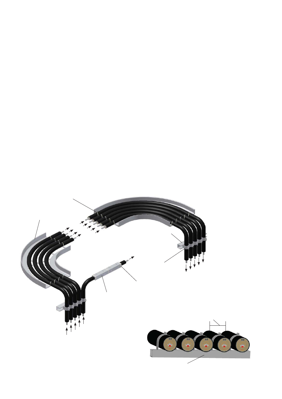
Illustration B: Typical Tube Bundle Installation
Standard
Cable Tray
Illustration C: Typical Installation
13mm
Minimum
2
1. TubeTrace tubing bundles may be installed in cable trays
or using individual strut channel.
2. Secure bundle with clamps or cable ties every 3 to 4.5m
on vertical runs. Do not deform bundle jacket while
securing tubing bundle to supports.
3. Allow expansion loop in tray every 30m to allow for
expansion and contraction of tubing bundle. Provide
300mm of slack for every 30m of tubing bundle run.
4. If the vertical run is offset around the stack, pull suffi cient
tubing bundle up the stack to make the offset, secure
bundle on the vertical run before routing the bundle
around the stack. Take extra precaution to not damage the
internal components of bundle. Stage multiple Kellems*
grips on vertical runs to reduce pulling tension on the
bundle.
* Kellems is a trade name of Hubbell Killark
TubeTrace
®
Tubing Bundles
INSTALLATION PROCEDURES