Tubetrace, Tubing bundles, Installation procedures – Thermon TubeTrace Tubing Bundles User Manual
Page 6: Tubing bundle attachment methods, Illustration e: typical vertical attachment
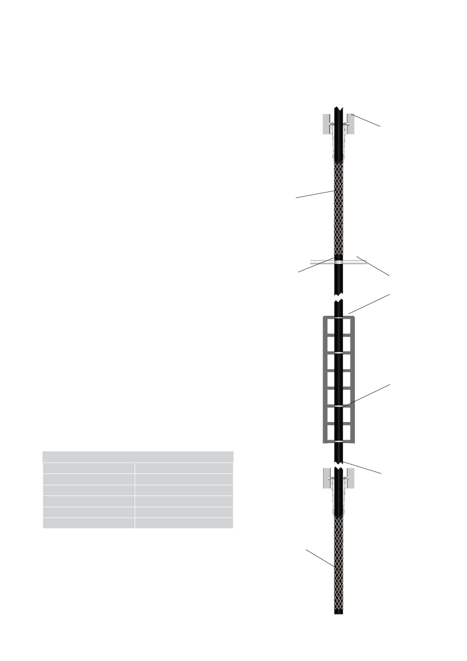
Table 2: Strut Clamp Selection
Nominal Bundle O.D.
Strut Clamp Size
25mm
32mm
32mm
38mm
41mm
51mm
67mm
64mm
86mm
76mm
92mm
89mm
Tubing Bundle Attachment Methods . . .
1. For ease on installation and maintenance, route multiple
runs of TubeTrace tubing bundles symmetrically utilizing
the most accessible path possible. Routing should take
advantage of existing cable trays, angles, channels, struts
and I-beams for support. Maintain a 76mm minimum
clearance between lines. Do not secure bundles to each
other.
2. After pulling bundle into position, insure suffi cient
bundle is available to make fi nal connections. Secure top
Kellems grip to support structure, with additional Kellems
grips located every 10.67m.
3. Allow expansion loop in tray every 30m for expansion
and contraction of TubeTrace tubing bundle. Provide
300mm of slack for every 30m of tubing bundle.
4. Secure TubeTrace tubing bundles to support structure
every 1.5 to 1.8m on horizontal straight runs and every
3 to 4.5m on vertical runs. Provide additional support
within 450mm of any connection point or transition
fi tting and within 150 to 250mm of any bends.
5. Cable trays and channel struts provide optimal support
for multiple passes of TubeTrace tubing bundle. Secure
bundle to cable tray using UV resistant plastic cable ties,
or preferably stainless steel bundle clamps or standard
conduit straps for channel strut attachment (see Table
2 for clamp sizing). Use caution when securing bundle
to structure. Do not deform or crush the thermal
insulation and outer jacket.
6. As an option, angle iron may be used to support
TubeTrace tubing bundles on long vertical and horizontal
runs. Angle iron should be sized approximately 12mm
larger than the tubing O.D. Place the angle over the
bundle to prevent moisture buildup. Secure bundle to
the angle using UV resistant cable ties or stainless steel
banding.
Illustration E: Typical Vertical Attachment
Kellems Grip
Channel Strut
or Cable Tray
(Typical)
Angle Iron, Channel
I-Beam (Typical)
Strut Clamp
(Typical)
Secure Bundle with
Kellems Grip Located
Every 10.67m
(Typical)
TubeTrace
Tubing Bundle
(Typical)
5
7. Before making power connection, the heat trace should
be tested to ensure electrical integrity with at least a 500
Vdc megohmmeter (megger) between the heat trace
bus wires and the metallic braid. IEEE 515 recommends
that the test voltage for polymer insulated heat trace be
2500 Vdc. Minimum resistance should be 20 megohms.
(Record 2 on Field Test Report)
After the power
connection is completed, temporarily energize heat
trace so that the energized test values can be recorded.
(Record 3 on Field Test Report)
UV Resistant
Plastic Cable Ties
(Typical)
TubeTrace
®
Tubing Bundles
INSTALLATION PROCEDURES