Tubetrace, Tubing bundles, Installation procedures – Thermon TubeTrace Tubing Bundles User Manual
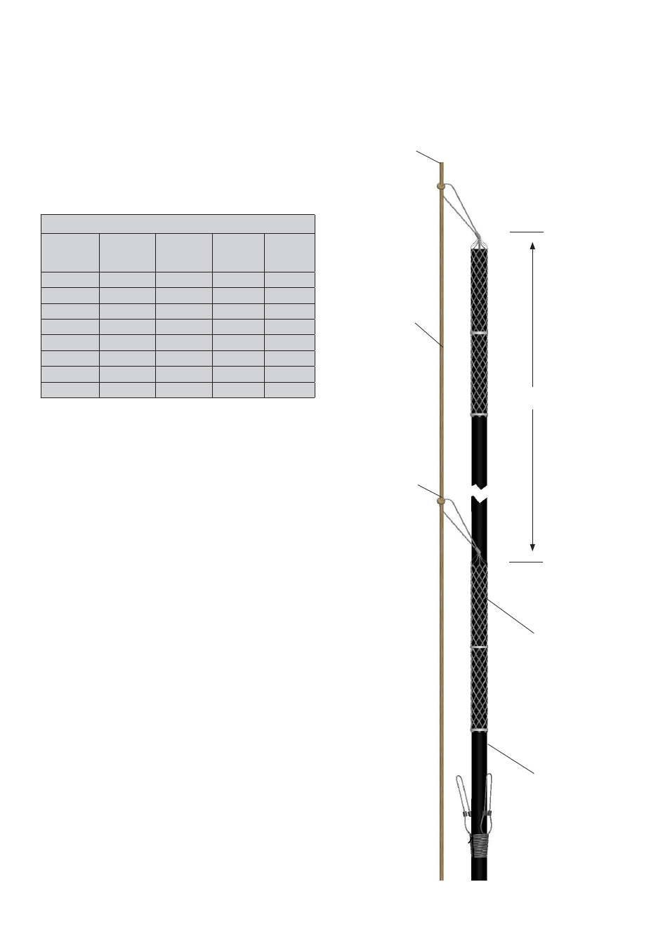
Page 5: Pulling procedures, Illustration d: pulling detail
Pulling Procedures . . .
1. The pulling line should be connected to the tube
bundle using an appropriate sized Kellems grip for your
application. Do not use a damaged grip for pulling bundle.
Pulling tension should not exceed 22.7kg, with a minimum
pulling line of 15mm.
4
Standard Kellems Double Eye Grips
Catalog
Number
Diameter
mm
Breaking
Strength
kg
Pulling Eye
Length
mm
Mesh Grip
Length
mm
022-01-005 25.4-31.5
730.28
127
355.6
022-01-006
31.75-37.85
730.28
127
381
022-01-007
38.1-44.2
730.28
127
431.8
022-01-008
44.45-50.55
975.22
152.4
482.6
022-01-009
50.8-63.25
1478.71
152.4
533.4
022-01-0010
63.5-75.95
1478.71
152.4
584.2
022-01-0011
76.2-88.65
2222.60
203.2
635
022-01-012
88.9-101.35
2222.60
203.2
685.8
2. Position tubing bundle reel at the top or base of the stack
in line with cable tray to reduce overall friction on pulling
run. Pulling should allow someone at the end to stop the
reel from turning when the pulling force is stopped.
3. Extreme pulling tension may tend to fl atten the tubes and
damage heat tracing as they round corners, etc. Observe
the minimum bending radius of the tubing bundle during
pulling operation. (Refer to Table 1 Bend Radius)
4. For rounding corners, a pulley or roller may be utilized
while passing over sharp edges that might damage the
bundle. Both the pulleys and rollers can be rented at many
electrical supply houses.
5. Kellems grips are required for permanently securing
the bundle to the stack every 10.67m. NOTE: Kellems
grips used for bundle installation will also be used to
permanently attach bundle to support structure.
6. After determining the total number of Kellems grips
required for permanent installation, slide grips required
over bundle as shown on Illustration D. Use duct tape
to prevent Kellems grips from slipping during bundle
installation.
7. Attach pull rope to the pulling eye in the Kellems grip.
Do not connect any type of hook, clamp or attachment
hardware to any other part of the grip.
8. Secure pulling rope to fi rst Kellems grip leaving suffi cient
line for additional grips as required. See pulling detail
illustration. Do not exceed spacing of 10.67m between
grips.
Pull Rope
U-Bolt
U-Bolt
10.67m
Illustration D: Pulling Detail
Kellems Grip
UV Resistant
Plastic Cable Ties
(Typical)
TubeTrace
®
Tubing Bundles
INSTALLATION PROCEDURES