Hardware setup and status leds – Teletronics EZPlatform User Manual
Page 6
6
4. Hardware Setup and Status LEDs
Hardware Setup
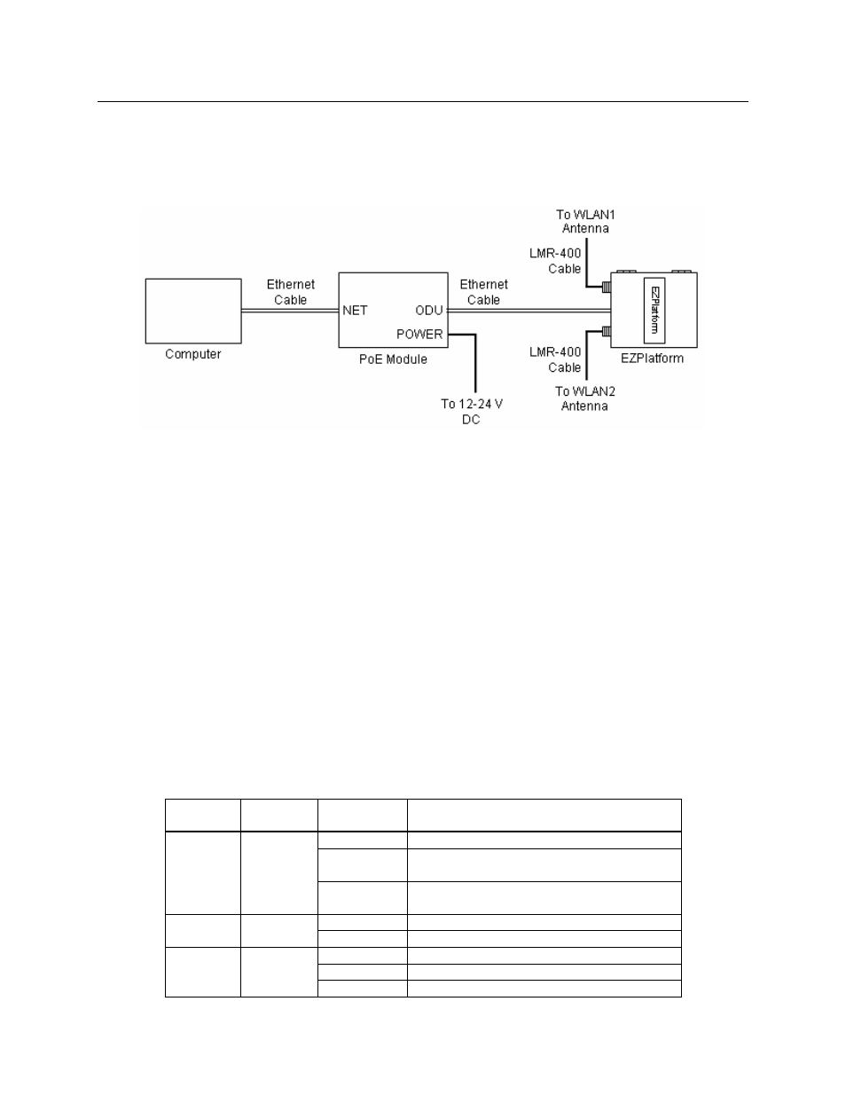
Figure 1 shows how to connect the EZPlatform™.
Figure 1. Network and power connections
The purpose of this setup is to connect the EZPlatform™ so that it can be configured with a
computer via the web interface of the EZPlatform™. The power over Ethernet (PoE) module
allows you to send/receive data and power the EZPlatform™ with a single cable. When
connecting the antennas, care must be taken so that the antennas are properly mounted to
avoid mutual interference, especially if both wireless interfaces will be operated in the same
802.11 mode.
WLAN1 and WLAN2 are the fixed designations for the two wireless interfaces. WLAN1 is wired
to the antenna port that is closer to the hinges of the NEMA 4 enclosure; WLAN2 is wired to the
antenna port farther from the hinges of the enclosure.
Status LEDs
The behavior of the LEDs mounted on the enclosure is explained in the following table.
LED Position Status
Interpretation
Off
Radio card not detected / wireless off
Blinking
No station(s) associated (in AP mode)
Not associated to an AP (in SU mode)
WLAN1 Left
Solid on
Station(s) associated (in AP mode)
Associated to an AP (in SU mode)
Off Power
off
Power Center
Solid on
Power on
Off
Radio card not detected / wireless off
Blinking No
station(s)
associated
WLAN2 Right
Solid on
Station(s) associated