Sdram, Flash – Sundance SMT374 User Manual
Page 10
Version 2.2
Page 10 of 29
SMT374 User Manual
A full description of the registers used to control the EM
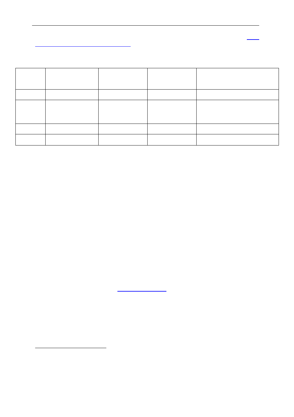
The standard bootstrap will initialise these registers to use the following resources:
Memory
space
Setting Resource
DSP-A
Resource
DSP-B
Address range
CE0 0x00000030
SDRAM
128MB
SDRAM 128MB
0x80000000 - 0x87FFFFFF
CE1 0xFFFFFF23 Flash
8MB
divided in
4x2MB pages
Virtex (2KB
DPRAM with the
Virtex)
0x90000000 - 0x901FFFFF
CE2 0x00100020
Control register
0xA0000000 - 0xA0000010
CE3 0x00000030
Virtex
Virtex
0xB0000000 - 0xB7FFFFFF
SDRAM
Memory spaces CE0 are used to access 128MB of SDRAM over the EMIF.
The speed of the SDRAM is dependent on the processor variant. Using the C6x11,
the SDRAM will operate at 100MHz.
Using the C6713, the SDRAM operates at a programmable rate up to the maximum
allowed on the EMIF (TI data sheet = TBD
).
The EMIF CE0 & CE3 memory space control registers should be programmed with
the value 0x00000030.
FLASH
An 8MB Flash ROM is connected to DSP-A in the EMIF CE1 memory space. It
cannot be accessed by DSP-B. The ROM holds boot code for the DSP, configuration
data for the FPGA, and optional user-defined code.
A software protection algorithm is in place to prevent programs accidentally altering
the ROM’s contents. Please
for further information about re-
programming this device.
The CE1 memory space control register should be programmed with the value
0xFFFFFF23. This is the same value for DSP-B, even though this DSP does not
have access to the flash. When DSP-B accesses memory on CE1, the Virtex will
respond with data within its internal dual port RAM (using the standard Sundance
Virtex configuration).
1
To Be Defined