Sundance SMT339 v.1.3 User Manual
Page 21
Version 1.2
Page 21 of 27
SMT339 User Manual V1.3
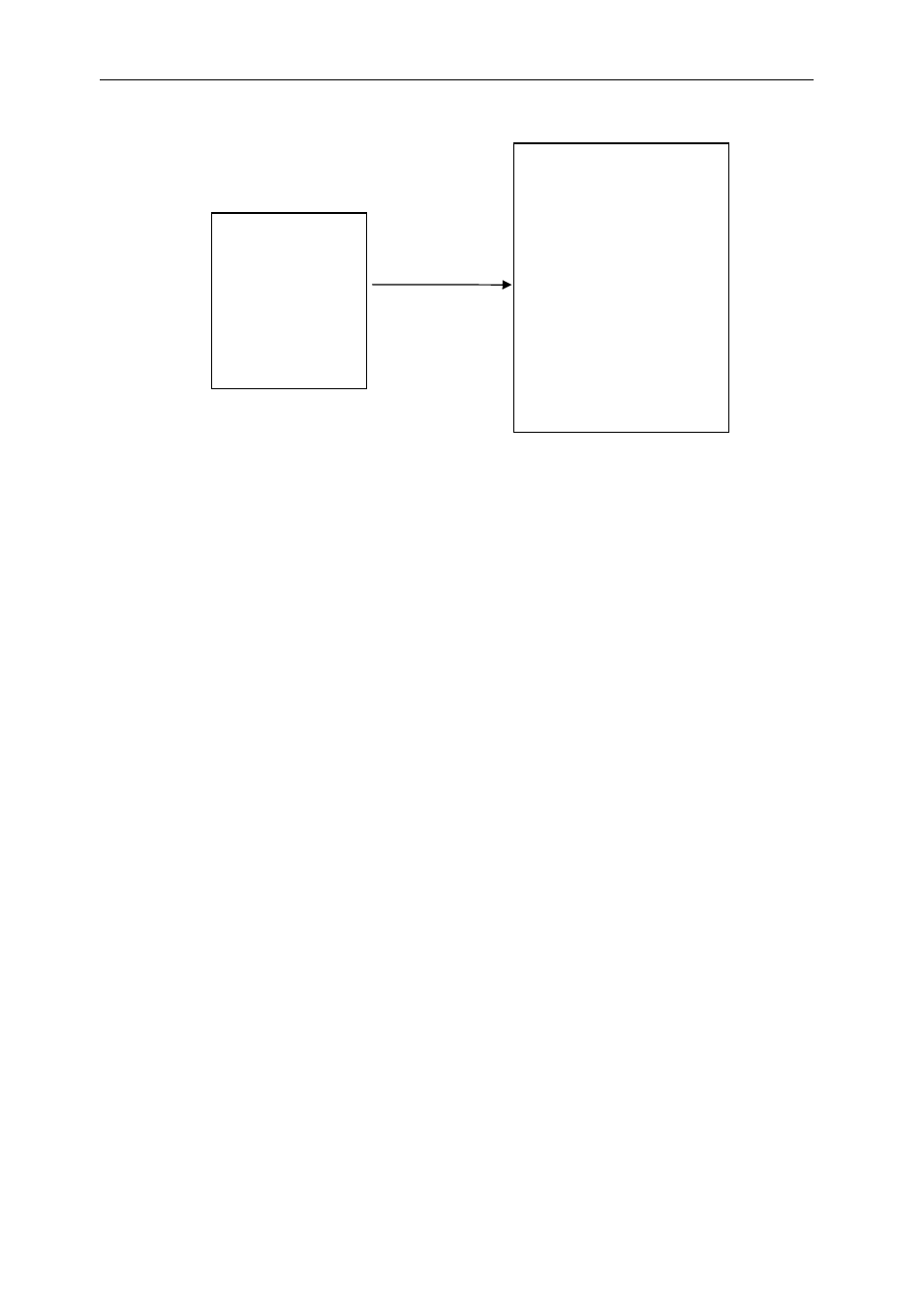
Figure 4 : RGB565 organisation of the video memory
3.1.2 EDMA
The next step is instruct the EDMA to transfer data the video data into the Video
Ports input FIFO channel. For the RGB656 format this will involve a single EDMA
channel. For the YCrCb format 3 separate EDMA channels require initialisation.
3.1.2.1 RGB656 Single Bank EDMA Setup
Requests to the EDMA controller are set by the Video Port Input FIFO threshold
levels.
Usually each request transfers a complete video line output.
DMA transfers are done 64-bits at a time as the video port input FIFO is 64-bits wide,
therefore, an even number of words must be transferred.
The Video Encode Register at 0xA0001 D000 bit 4 must be set to ‘1’ when in
RGB656 output mode. This allows demultiplexing of the data before being sent to the
Encoder.
3.1.2.2 BT656 with embedded Sync EDMA Setup
Three separate EDMA channels must me setup for this mode. One for the Y channel,
one for the Cr channel and one for the Cb channel.
Bank 1
RGB Data
20-bit Element-
Lower 16 bits
encoded
RGB565
EDMA Controller