3 video ports – Sundance SMT339 v.1.3 User Manual
Page 19
Version 1.2
Page 19 of 27
SMT339 User Manual V1.3
User Manual (QCF42); Version 1.2, 8/11/00; © Sundance Multiprocessor Technology Ltd. 1999
3 Video
Ports
The SMT339 has 3 video ports connected from the DSP to the Virtex 4 FPGA. Video
port 0 is, by default, routed to the video decoder and video port 1 is connected to the
video encoder. Video Port 1 is unused in the default fpga configuration and is
reserved for upgraded firmware when the SMT339 is used with carrier boards such
as the SMT114, or SLB cards such as the SMT339. The port is reserved for either:
an extra video input/output or, the port is reserved for use as a SPI interface.
This section describes how to set the video port hardware and software up for basic
operation. For further detailed information please refer to the relevant TI
documentation
(TMS320C64x DSP Video Port/ VCXO Interpolated Control (VIC) Port
Reference Guide )
.
3.1 Video Encoder Setup
The video encoder has a wide rage of operational features; such has output format,
lookup tables, and cursor insertion and colour space conversions. This section
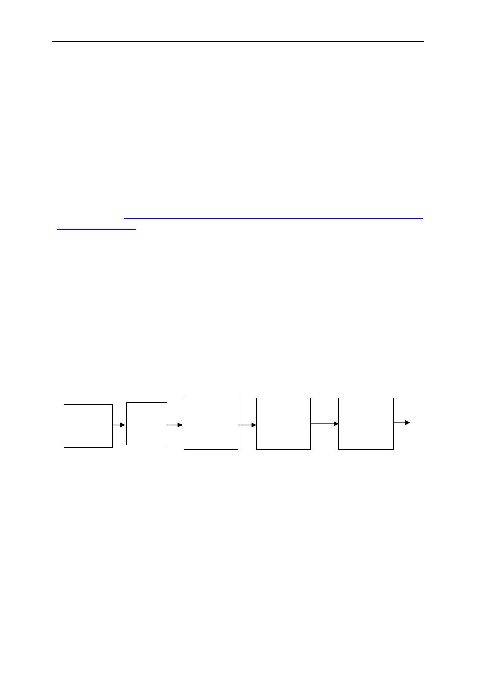
describes the basics operation of the encoder. The figure below illustrates the flow
from data in DSP memory to final output by the encoder together with the necessary
stages that require initialising.
Figure 2 : Flow from Video Memory to Encoder
Encoder
FPGA
Video
Port
EDMA
Video
Memory