Rs485, Led rsl shb rs485 – Sundance SMT148 User Manual
Page 30
Version 1.4
Page 30 of 35
SMT148 User Manual
LED
The LED interface is only a slave output node and turns on or off the 32 LED on the
carrier depending on the settings it receives. The LED interface expects only one 32-
bit word and will disconnect itself automatically from the input node after it received it
(meaning that a DONE pulse is sent to the switch fabric).
Bit 8: indicate the LED value, on if 1, off if 0.
Bit 4 down to 0: LED address.
RSL
The RSL interface is compliant to the Sundance RSL specifications. A fast bi-
directional data pipe can be connected between the RSL interface and the SHB
interface for data conversion from one to the other.
SHB
The SHB interface is compliant to the Sundance SHB specifications and protocol.
RS485
The RS485 interface is an output node as well as an input node to the switch fabric.
The first 32-bit word received by this interface defines the transfer direction of the 2
bytes connected to RS485 transceivers on the carrier board. It also defines the
length of the transfer for both bytes and the address of the output node (in the case
one of the bytes is set as an output).
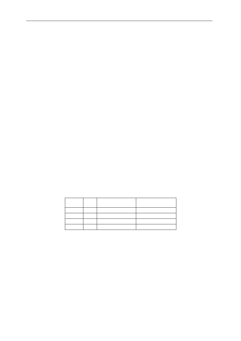
Bit 31
Bit30
Byte 1
(bit 15 down to 8)
Byte 0
(bit 7 down to 0)
0 0
Output
Output
0 1
Output
Input
1 0
Input
Output
1 1
Input
Input
Table 22 : RS485 settings
Bit 29 down to 16: Bytes transfer length (if length=0, the transfer will never end)
Bit 7 down to 0 : Output node address in the case one or both bytes are set as an
input to the system.
On the FPGA IO side, in addition to the 2 bytes, 2 signals controlled by the settings
allow to set the transceivers directions on the carrier.