Rs485, Rs485 rsl shb – Sundance SMT148 User Manual
Page 15
Version 1.4
Page 15 of 35
SMT148 User Manual
RS485
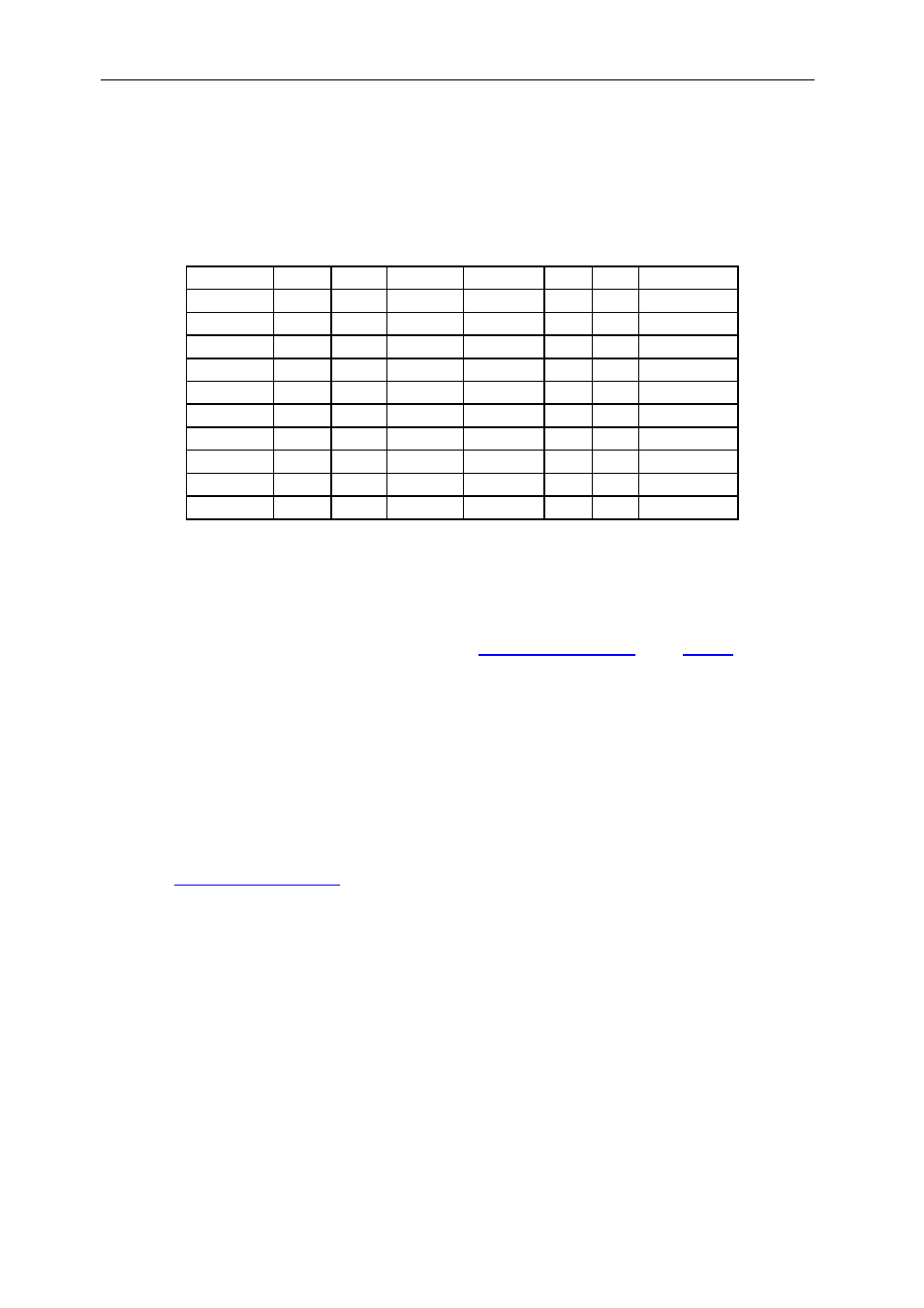
16 bi-directional RS485 pairs are connected to the FPGA. Each byte direction is
controlled by the firmware. The RS485 driver/receivers are connected to a SDB type
connector (40 way). The connector pinout is as follow:
Function pin pin Function Function pin pin Function
S0- 1
2
S0+
GND
21
22
GND
S1- 3
4
S1+
GND
23
24
GND
S2- 5
6
S2+
S8-
25
26
S8+
S3- 7
8
S3+
S9-
27
28
S9+
S4- 9
10
S4+
S10-
29
30
S10+
S5- 11
12
S5+
S11-
31
32
S11+
S6- 13
14
S6+
S12-
33
34
S12+
S7- 15
16
S7+
S13-
35
36
S13+
GND 17
18
GND
S14-
37
38
S14+
GND 19
20
GND
S15-
39
40
S15+
Table 10: RS485 pinout
RSL
A RSL link is available on the carrier and can allow users to transfer up to 20Gb/s of
data in full duplex mode. This ultra high speed transfer link uses the dedicated
Rocket IO from the Xilinx
d
for more
details.
SHB
One 60-pin SHB connector (Samtec QSH-030-01) is connected to the FPGA. It can
be used for debugging purposes and connected to a Logic Analyser using some
specific adapters.
It can also be used as a high speed link to transfer data to the FPGA carrier and TIM
modules using the SDB protocol (2x 200Mbytes/s). For this configuration, please
.