Switch fabric – Sundance SMT148 User Manual
Page 20
Version 1.4
Page 20 of 35
SMT148 User Manual
Switch Fabric
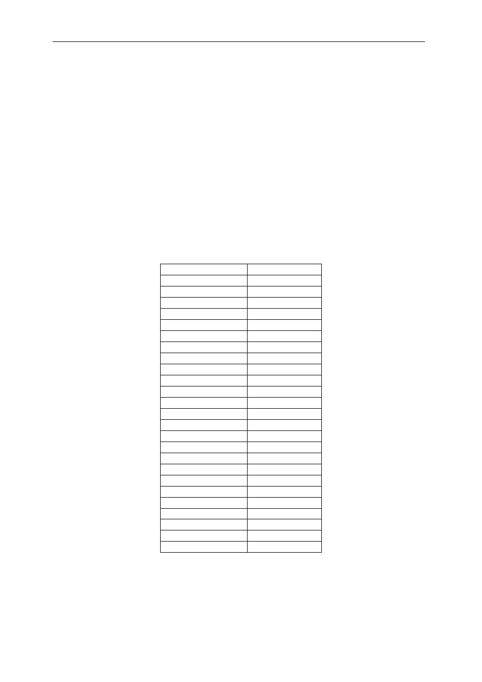
Due to the high number of interfaces to be implemented in the firmware it is important
to keep the design scalable and flexible. The switch fabric is a digital component that
could be seen as a giant multiplexer/demultiplexer and that allows to dynamically
connect the different interfaces to each others. The switch fabric will run on the
FPGA system clock (100MHz by default) and will therefore not become the
bottleneck for any transfer. It has multiple input nodes and output nodes operating
under a protocol disregarding the specificities of the interfaces it is connected to. The
node data/address bus is 8-bit wide plus few control signals. Any input node can
target any output node but one input node can be remotely connected to only one
output node at a time. When a transfer is about to be started by a specific interface
(input node) the first word received on the switch fabric input node will be the address
of the output node it needs to access. Three bytes of zeros will then be sent after the
address byte. The data/address/control words that will follow will be sent to the
output node and must comply with the specific format of the targeted interface.
Output node
Address (Hex)
ComPort_0 (TIM1)
00
ComPort_1 (TIM1)
01
ComPort_2 (TIM2)
02
LED 03
ComPort_4 (TIM3)
04
DAC 05
ComPort_6 (TIM4)
06
μcontroller1 07
McBSP TIM1
08
McBSP TIM2
09
McBSP TIM3
0A
McBSP TIM4
0B
Watchdog timer TIM1
0C
Watchdog timer TIM2
0D
Watchdog timer TIM3
0E
Watchdog timer TIM4
0F
RS485 10
μcontroller2 11
RSL 12
SHB 13
ComPort_3 (TIM2)
14
ComPort_5 (TIM2)
15
ComPort_7 (TIM2)
16
ADC 17
Switch Fabric
F0
Table 14 : Output nodes addresses