Power out, Jtag, Fan power – Sundance SMT148 User Manual
Page 17: Reset scheme, Jtag led fan power reset scheme
Version 1.4
Page 17 of 35
SMT148 User Manual
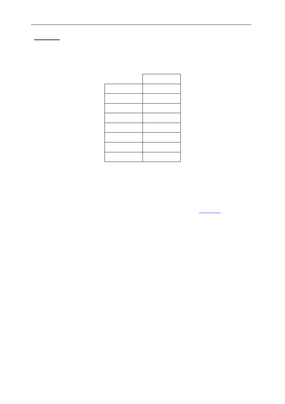
Power out
Power can be supplied to external devices or modules. The 8-pin connector
(Receptacle, mini fit 8 Way, Molex), providing different voltages, has the following
pinout:
Pin
number
-12V 1
+12V 2
+5V 3
+3.3V 4
GND 5
GND 6
GND 7
GND 8
Table 12 : Power out pinout
JTAG
A single JTAG chain connects all 4 TIM sites and the JTAG in & out connectors. This
chain is used with the TI Code Composer Studio software suite.
The JTAG-out (JTAG2) connector can be connected to the JTAG-in (JTAG1)
connector of other SMT148, thus extending the chain (see cable
).
LED
A 8x4 array of LED is connected directly to the FPGA and is controlled by the FPGA
firmware
Fan Power
Eight two-pin connectors are provided to supply fans with a +12V supply.
Reset Scheme
A power rail monitor observes the state of the 3.3V supply. This device will generate
a reset to the SMT148 (RESET148) during power-up or if the 3.3V supply drops
below 3V. This signal is an open-collector output and is also driven to the inter-card
ComPort connector, and thus to another SMT148.
The POR (power on reset) signal is driven to the RESETOUT pin on the external
ComPort1 connector. The RESETIN pin on the above connector is buffered by an
open-collector device which in turn can also drive the RESET148 signal. An
additional 4 pin header is provided to allow other devices to share the open-collector
RESET148 signal.
The TIM reset pins are connected to the FPGA and will be reset when RESET148 is
active as well as when some firmware conditions trigger a reset to the different TIMs
(see Firmware description for more details about TIM reset).