Master/slave configuration, Figure 12 - master/slave configuration, 6 master/slave configuration – Sundance SMT6012 v.4.6 User Manual
Page 19
Version 4.6
Page 19 of 22
SMT6012 User Manual
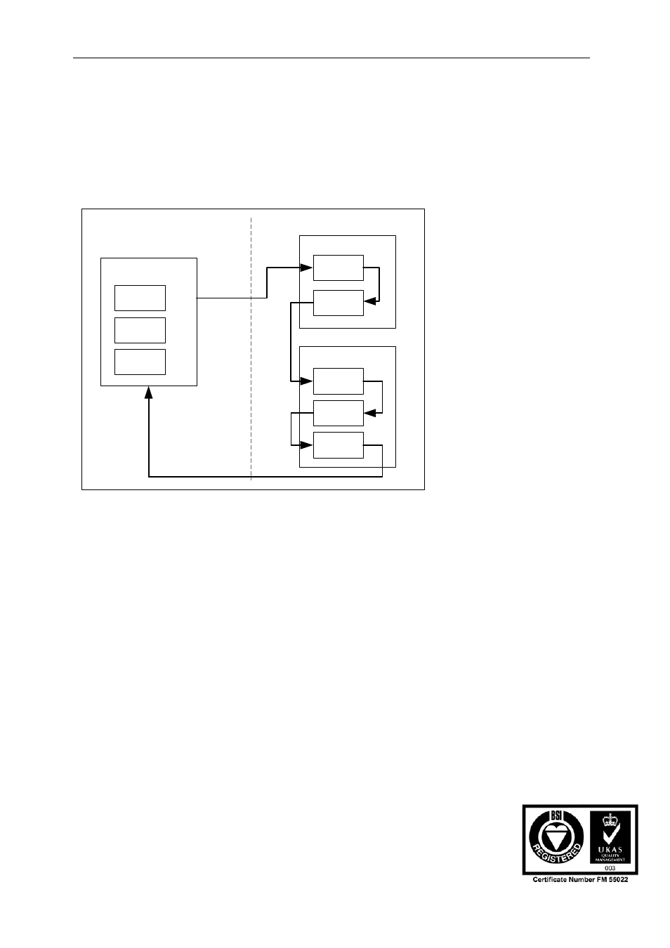
6 Master/Slave
configuration
It is possible to use a carrier board as a master board that is used to debug a slave
board in a remote system. In this case the slave boards have to be part of the JTAG
chain of the master board. The figure below shows such a configuration. Each
processor on the slave boards has to be specified in the CCS setup. Ensure that
CCS is set up to point to the master carrier board.
Master carrier board
First slave board
Remote system
Debugging host system
Processor 1
Processor 2
Second slave board
Processor 1
Processor 2
Processor 3
External
JTAG
chain
Processor 1
Processor 2
Processor N
Figure 12 - Master/Slave configuration
The figure below shows the CCS setup for the sample configuration shown above.
User Manual (QCF42); Version 4.6, 26/06/02; © Sundance Multiprocessor Technology Ltd. 2002