Studio Technologies 55 2002 User Manual
Page 13
Model 55/56 User Guide
Issue 4, June 2002
Studio Technologies, Inc.
Page 13
Mounting the Model 55
The Model 55 requires one space in a
standard 19-inch (48.3cm) equipment rack.
Select a location near where the Model 56
Control Console will be located. A cable is
provided to connect the Model 55 to the
Model 56. You can supply a longer cable,
however 50 feet (15.3m) is the recom-
mended maximum length. It is desirable to
locate the Model 55 to allow easy access
to both the front and the back panels. The
back panel contains all of the input and
output connectors, while the front panel
contains several LED indicators. The
Model 55 is secured to the equipment rack
using two mounting screws per side.
Audio Inputs and Outputs
The Model 55’s line-level audio input and
output connections are made using ¼-inch
3-conductor phone jacks. For reliable
audio interconnection, the plugs you use
must comply with industry standard RS-
453. Switchcraft No. 297, Neutrik NP3C, or
equivalent will work correctly.
Stereo Line Inputs
The Model 55 provides four stereo line-
level inputs. Each input is electronically
balanced, and can be configured for com-
patibility with –10dBV or +4dBu signal
levels. The Model 56 Control Console
gives you push-button control, so you can
easily change input sensitivities at any
time (refer to the Configuration section
under Input Sensitivity). Monaural sources
should be connected to the left (L) input
and configured for mono operation (refer
to the Configuration section under Stereo/
Mono Input).
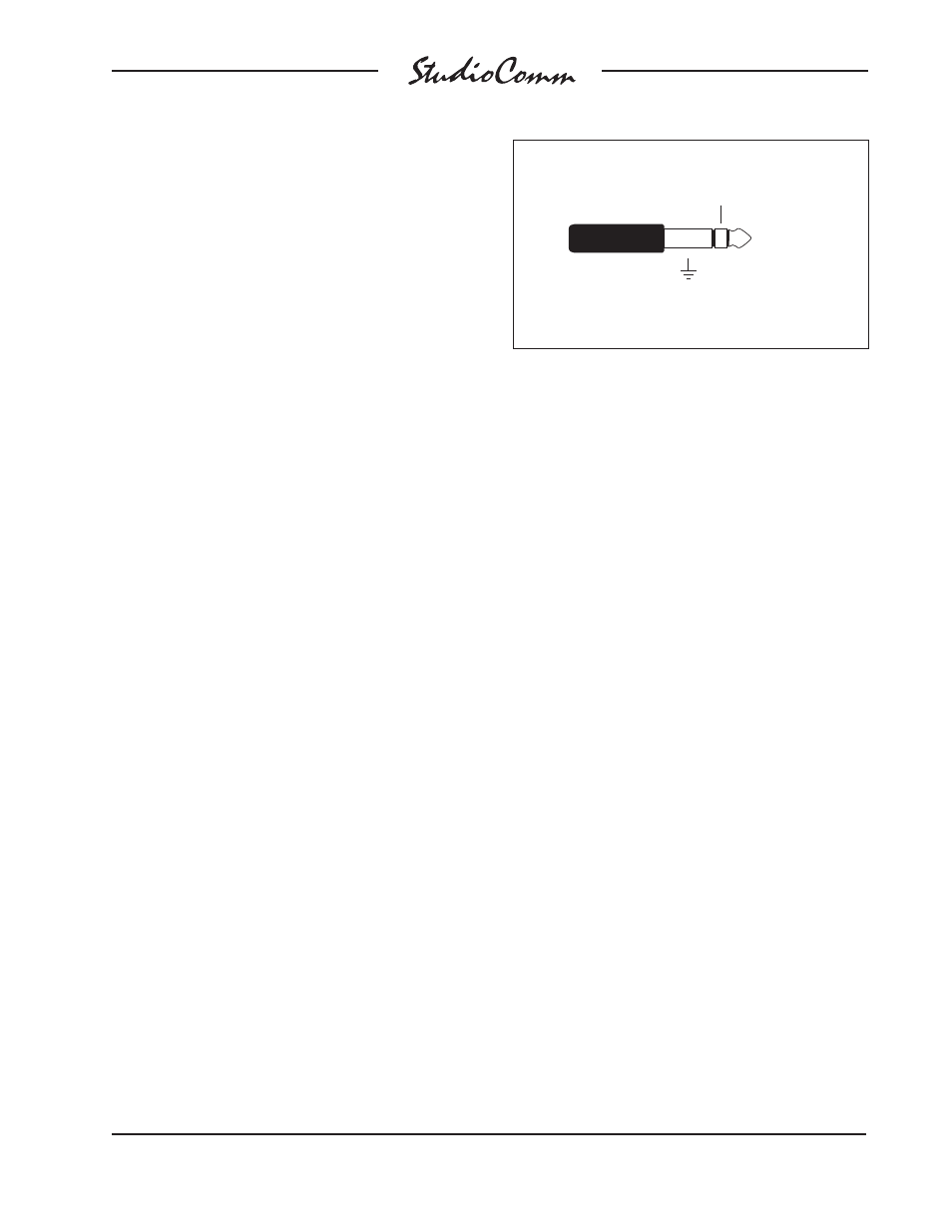
Prepare the mating connectors (plugs)
so that tip is signal high (+ or hot), ring is
low (– or cold), and sleeve is shield. With
an unbalanced source connect the tip to
high (+ or hot), and both the ring and
sleeve to shield. If connecting to an
unbalanced source in this manner results
in hum or noise, connect tip to high (+ or
hot) and ring to shield; leave the sleeve
unterminated.
Control Room Output
The Model 55 contains a stereo line-level
output for connection to an audio power
amplifier. This audio amplifier serves a
pair of loudspeakers that are located in the
control room. (Of course the control room
output can be connected to loudspeakers
that contain integral power amplifiers, such
as the products from Genelec.)
The output is electronically balanced and
capable of driving loads of 600 ohms
or greater. In most situations best perfor-
mance will be obtained if the audio amp-
lifier’s input sensitivity is set to near
maximum. Refer to the Technical Notes
section for details on setting amplifier
sensitivity.
The control room output utilizes two
¼-inch 3-conductor phone jacks for inter-
connection. Prepare the mating connec-
tors (plugs) so that tip is signal high (+ or
hot), ring is low (– or cold), and sleeve is
shield. To connect to an unbalanced load
connect the tip to high (+ or hot), and both
the ring and sleeve to shield.
Balanced Input and Output Connections
Sleeve: Shield
(Switchcraft No. 297, Neutrik NP3C, or equivalent)
Tip: +
Ring: –