Installation – Studio Technologies 55 2002 User Manual
Page 12
Issue 4, June 2002
Model 55/56 User Guide
Page 12
Studio Technologies, Inc.
Installation
In this section you will be installing the
Model 55 Central Controller in an equip-
ment rack. Audio input and output connec-
tions will be made using the Model 55’s
multitude of jacks. One or more Model 35
or Model 38 Talent Amplifiers may be
connected. A location will be selected for
the Model 56 Control Console, and it will
be connected to the Model 55. AC mains
power will be connected to the Model 55.
System Components
The main StudioComm shipping carton
contains a Model 55 Central Controller,
Model 56 Control Console, 5-conductor
MIDI-style cable, User Guide, and warranty
card. Units destined for North America are
shipped with an AC mains cord. Your
dealer or distributor will provide an AC
mains cord for non-North American desti-
nations. Model 35 and Model 38 Talent
Amplifiers, along with accessories, will be
contained in separate cartons. Please
check to ensure you have everything you
need.
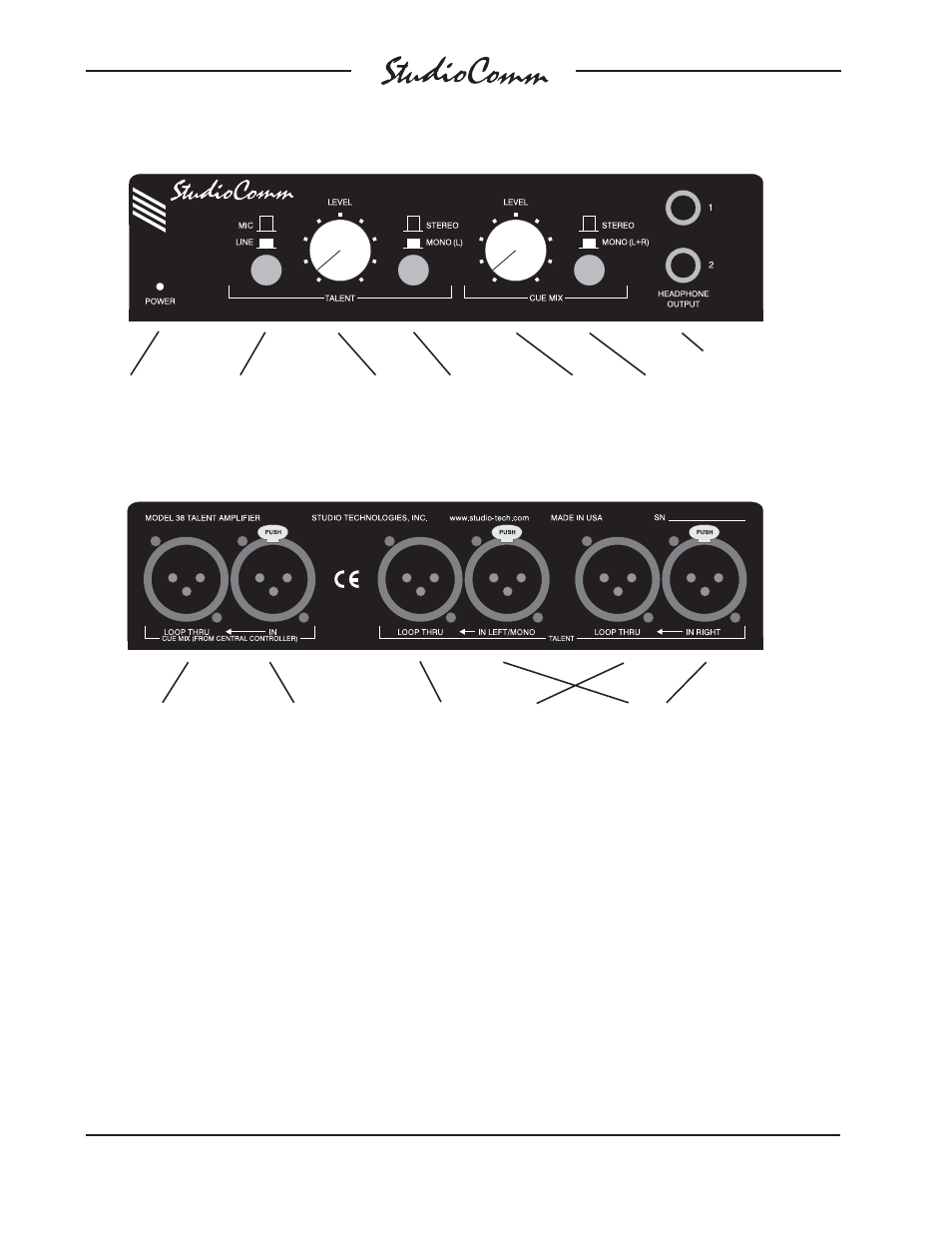
Talent level
to phones
Power present
LED
Mic/Line button switches
the talent input between
microphone and line level
Model 38 Front Panel
Switch between
stereo and mono
(L only) for the
talent input
Cue mix
level to
phones
Switch between stereo
and mono (L+R) for
the cue mix
Two headphone outputs
Model 38 Back Panel
Connects to talent
sources such as key-
boards or microphones
Loop thru connectors parallel the
talent inputs for routing to a digital
audio workstation, effects device,
microphone preamp, etc.
Connects to the
Model 55 or another
talent amplifier’s loop
thru connector
Connects to additional
talent amplifiers