Installation – Studio Technologies 55 2005 User Manual
Page 11
Model 55/56 User Guide
Issue 5, August 2005
Studio Technologies, Inc.
Page 11
Installation
In this section you will be installing the
Model 55 Central Controller in an equip-
ment rack. Audio input and output connec-
tions will be made using the Model 55’s
multitude of jacks. One or more Model 35
Talent Amplifi ers may be connected. A
location will be selected for the Model 56
Control Console, and it will be connected
to the Model 55. AC mains power will be
connected to the Model 55.
System Components
The main StudioComm shipping carton
contains a Model 55 Central Controller,
Model 56 Control Console, 5-conductor
MIDI-style cable, User Guide, and warranty
card. Units destined for North America are
shipped with an AC mains cord. Your dealer
or distributor will provide an AC mains cord
for non-North American destinations. Model
35 Talent Amplifi ers, along with accesso-
ries, will be contained in separate cartons.
Please check to ensure you have every-
thing you need.
Mounting the Model 55
The Model 55 requires one space in a
standard 19-inch (48.3 cm) equipment
rack. Select a location near where the
Model 56 Control Console will be located.
A cable is provided to connect the Model 55
to the Model 56. You can supply a longer
cable, however 50 feet (15.3 m) is the rec-
ommended maximum length. It is desirable
to locate the Model 55 to allow easy access
to both the front and the back panels. The
back panel contains all of the input and
output connectors, while the front panel
contains several LED indicators. The Model
55 is secured to the equipment rack using
two mounting screws per side.
Audio Inputs and Outputs
The Model 55’s line-level audio input
and output connections are made using
¼
-inch 3-conductor phone jacks. For reli-
able audio interconnection, the plugs you
use must comply with industry standard
RS-453. Switchcraft No. 297, Neutrik
NP3C, or equivalent will work correctly.
Stereo Line Inputs
The Model 55 provides four stereo line-
level inputs. Each input is electronically
balanced, and can be confi gured for com-
patibility with –10 dBV or +4 dBu signal
levels. The Model 56 Control Console
gives you pushbutton control, so you
can easily change input sensitivities at
any time (refer to the Confi guration section
under Input Sensitivity). Monaural sources
should be connected to the left (L) input
and confi gured for mono operation (refer
to the Confi guration section under Stereo/
Mono Input).
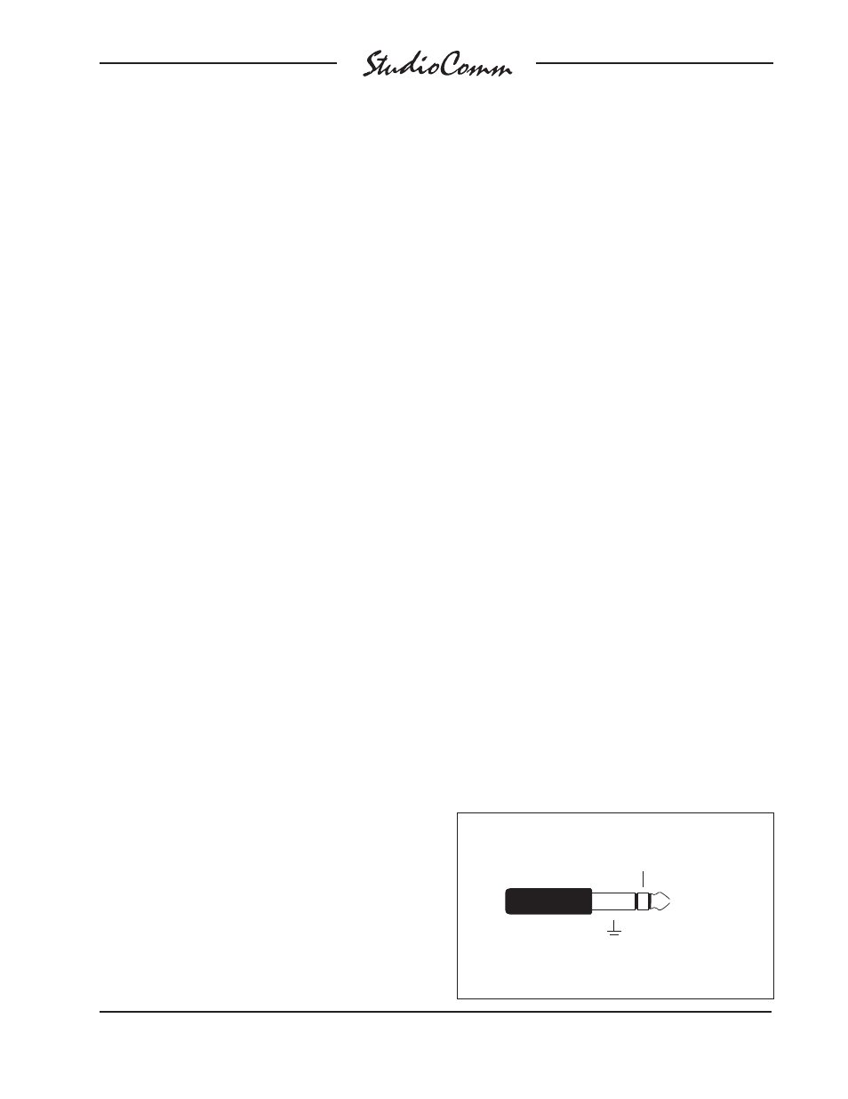
Prepare the mating connectors (plugs)
so that tip is signal high (+ or hot), ring is
low (– or cold), and sleeve is shield. With
an unbalanced source connect the tip
to high (+ or hot), and both the ring and
sleeve to shield. If connecting to an
unbalanced source in this manner results
in hum or noise, connect tip to high (+ or
hot) and ring to shield; leave the sleeve
unterminated.
Balanced Input and Output Connections
Sleeve: Shield
(Switchcraft No. 297, Neutrik NP3C, or equivalent)
Tip: +
Ring: –