Not a tw-12b replacement – Studio Technologies 47 User Manual
Page 27
Model 47 User Guide
Issue 1, August 2010
Studio Technologies, Inc.
Page 27
FLASH memory. This non-volatile memory
is used to store the operating software
(“firmware”). Re-programming this mem-
ory requires using a specialized program-
ming unit. While not outrageous in price,
it still costs in the range of US$500. The
“programmer” uses a ribbon cable and
socket to interface with a 6-pin “header”
on the Model 47’s printed circuit board.
And, as you would guess, once connect-
ed, re-programming takes only a matter of
seconds. But unfortunately the program-
mer is not something that would be found
in a typical “field shop” or repair facility.
Not a TW-12B Replacement!
The Model 47 will provide a high level of
performance over its range of intended
tasks. But it’s not intended to act as a “uni-
versal” 2-wire-to-2-wire interface such as is
provided by the venerable Clear-Com TW-
12B. The Model 47’s 2-wire interfaces are
not isolated from each other; they share
the Model 47’s internal power supply’s
common connection. (The power supply’s
common point is DC isolated from chas-
sis and earth ground.) Specifically, pin
1 on the XLR connector associated with
interface 1’s 2-wire party-line interface is
electrically connected to the pin 1 con-
nection on interface 2. This is due to the
fact that both 2-wire party-line interfaces
are capable of supplying DC power to
connected devices. They also use the
resources of a single set of logic circuitry.
And as such they each require access to
the Model 47’s common power supply
circuitry. There’s no doubt that a Model 47
could be used to create a 2-wire-to-2-wire
party line “bridge” by cross-linking the
4-wire inputs and outputs using standard
XLR audio cables. But it’s likely that a sig-
nificant “ground loop” would be created
through pin 1 of each of the Model 47’s
2-wire interfaces. While it’s possible to use
a set of special isolation transformers to
eliminate the ground loop, that’s best left
to the brave of heart!
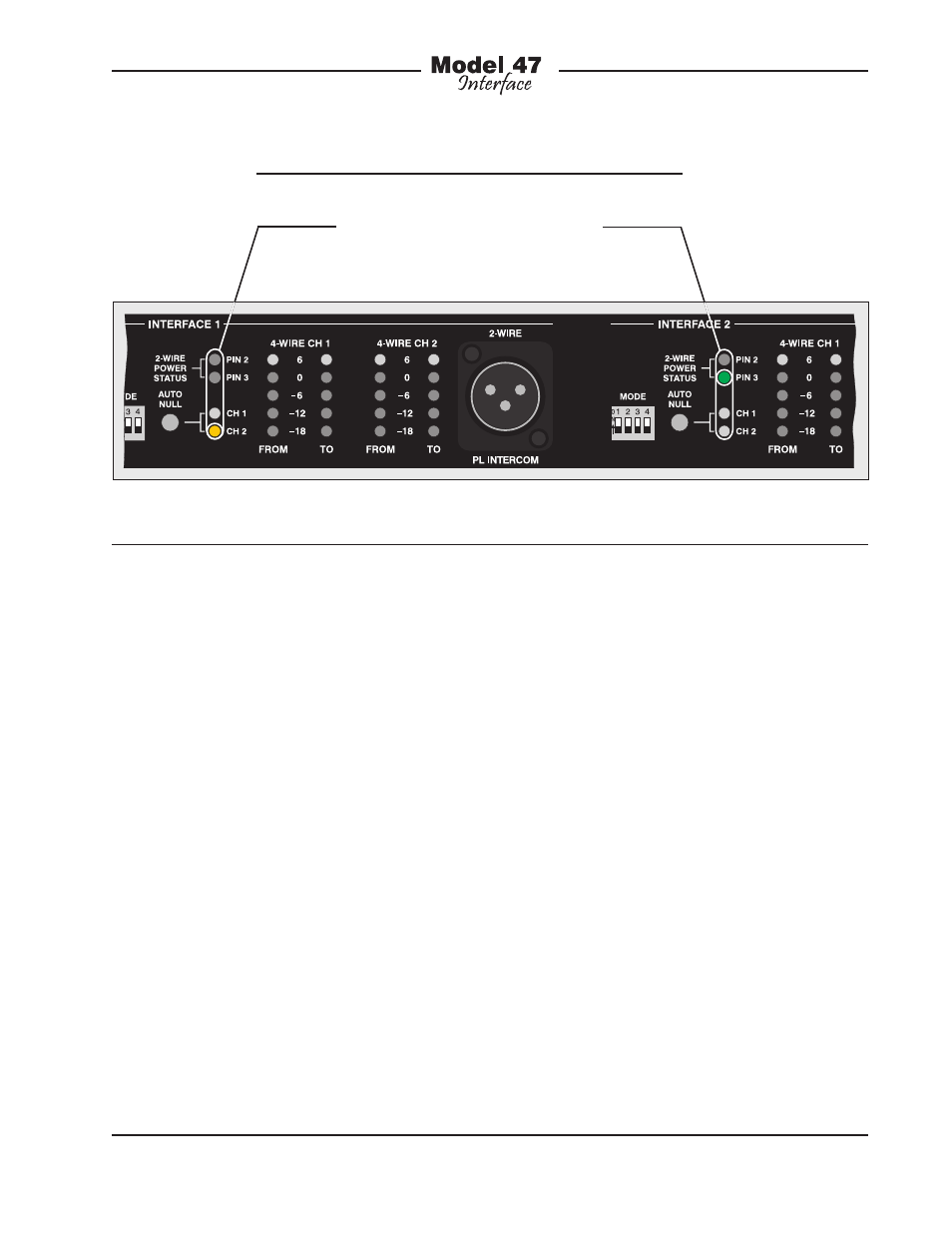
Figure 12. Detail of front panel showing the status LEDs that display the software version. In this
example, the software version is 1.3.
Interface 1 LED Section
Interface 2 LED Section
(Major Release Number)
(Release Sub-Number)
O
4
.4
O
O
3
.3
O
2
.2
O
1
.1
O