Configuration, Configuration – interface 1 and interface 2 – Studio Technologies 47 User Manual
Page 16
Issue 1, August 2010
Model 47 User Guide
Page 16
Studio Technologies, Inc.
Safety Warning: The Model 47 does
not contain an AC mains disconnect
switch. As such, the AC mains cord
plug serves as the disconnection de-
vice. Safety considerations require that
the plug and associated inlet be easily
accessible to allow rapid disconnec-
tion of AC mains power should it prove
necessary.
As soon as AC mains power is applied
the Model 47 will begin its power-up
sequence. As a “boot up” indication the
power LED and each of the status LEDs
will momentarily light. After the sequence
has completed the power LED will again
light and remain lit. The unit is now fully
functional.
Configuration
For the Model 47 to support the needs
of specific applications a number of op-
erating parameters must be configured.
These include the 2-wire party-line power
source, the nominal 2-wire level, and the
nominal 4-wire level. Three 4-position DIP
switch assemblies are used to establish
the desired configuration. One DIP switch
assembly is associated with interface 1, a
second is associated with interface 2, and
a third is associated with advanced oper-
ating features that apply to both interfaces.
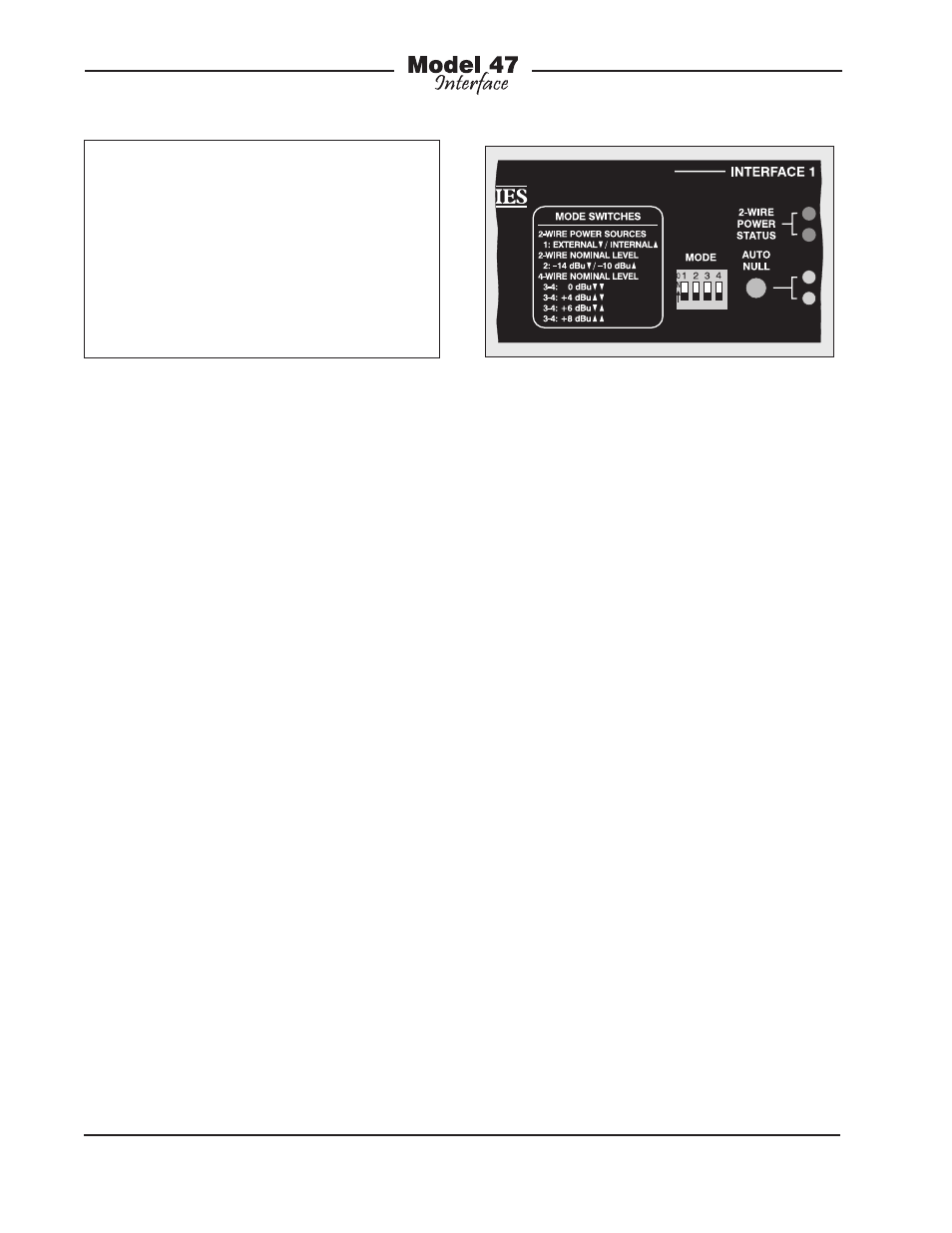
Configuration – Interface 1
and Interface 2
The DIP switch assemblies associated
with interfaces 1 and 2 are accessible on
the Model 47’s front panel. They provide
identical capability for their respective
interfaces. Refer to Figure 5 for a detailed
view. In this section the four DIP switches
associated with interface 1 will be covered
in detail. This information applies to inter-
face 2 as well. The four DIP switches allow
selection of the 2-wire party-line power
sources, the nominal level for the 2-wire
party-line channels, and the nominal level
of the 4-wire inputs and outputs.
2-Wire Party-Line Power Source
DIP switch 1 is used to select whether or
not the Model 47 provides DC power to
pins 2 and 3 of connectors associated
with the 2-wire party-line intercom chan-
nels. Two 3-pin male XLR connectors, one
located on the Model 47’s front panel and
one on the back panel, are used to inter-
connect the Model 47 with the intercom
user devices or a SAP. When DIP switch 1
is in its off (down) position the Model 47
will not provide DC power. This DIP switch
setting is appropriate when an external
intercom power supply is providing power
to the intercom circuit. In addition to power,
it’s expected that the external power supply
will also provide the required 200 ohm ter-
minating impedance to both pins 2 and 3.
When DIP switch 1 is in its on (up) position
the Model 47 provides independent 30 volt,
300 milliamperes maximum sources of DC
Figure 5. Detail of front panel showing four DIP
switches