Operation, Level meters – Studio Technologies 47 User Manual
Page 21
Model 47 User Guide
Issue 1, August 2010
Studio Technologies, Inc.
Page 21
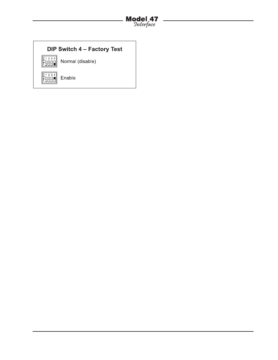
in the field DIP switch 4 should remain in
its off (down) position. No damage to the
Model 47 or connected equipment will
occur when factory test mode is active.
Operation
Technician intervention is typically not
required during normal Model 47 opera-
tion. The unit is designed for continuous
operation with no routine maintenance nec-
essary. Activating the auto null functions
may be warranted should connected user
devices or wiring associated with the 2-
wire party-line intercom be changed. Upon
power-up the Model 47 will go through a
short initialization sequence before normal
operation will begin. The power and status
LEDs will each light sequentially and, upon
completion, the power LED will light steadi-
ly. The settings for the four hybrid circuits
are stored in non-volatile memory and will
be recalled during the power-up process.
Level Meters
The Model 47 contains eight 5-segment
LED level meters. These meters are provid-
ed as a support aid during installation, con-
figuration, operation, and troubleshooting.
The meters represent the signals coming
in from, and going out to, the 4-wire con-
nections. The meters are organized in four
groups each representing one input and
one output. They are calibrated to reflect
the level in dB relative to the configured
nominal operating level. This is similar to
the way in which now-legacy VU meters
functioned. As an example let’s take the
situation where the nominal operating lev-
el of an interface is configured for +4 dBu
and an output (“to 4-wire”) LED labeled
“0 dB” is lit. (For this example, the level on
the 2-wire PL circuit is just large enough to
light the “0” LED.) This indicates that a sig-
nal with an approximate level of +4 dBu
is present on the associated 4-wire output
connector. Another example would be a
Model 47 interface configured for +8 dBu
operation and a –12 dB LED is lit. This
indicates that a signal with audio level of
–4 dBu is present on its associated output.
Each level meter contains four green
LEDs and one yellow LED. The four green
LEDs indicate signal levels at or below the
configured nominal level. The top LED is
yellow in color and indicates a signal that
is 6 dB or greater than the nominal level.
An audio signal that causes the yellow
LED to light doesn’t necessarily indicate
an excessive level condition, but it does
provide a warning that at some point
reducing the signal level may be prudent.
Normal operation with normal signal levels
should find the meters lighting near their
0-dB point. Signal peaks may cause the
yellow LEDs to flash. But a yellow LED that
lights fully during normal operation will
typically indicate a signal level or configu-
ration problem.
If the “from 4-wire” meters display con-
sistency lower or higher levels than their
0-dB points it’s possible that a configura-
tion issue exists. One potential problem is
incorrectly set 4-wire nominal audio level
DIP switches for one or both of the Model
Figure 10. DIP Switch 4—Factory Test