Wire party-line intercom connections – Studio Technologies 47 User Manual
Page 12
Issue 1, August 2010
Model 47 User Guide
Page 12
Studio Technologies, Inc.
2-Wire Party-Line Intercom
Connections
The Model 47’s 2-wire party-line (PL) inter-
com interfaces can be directly connected
with standard single- and dual-channel
party-line intercom devices. But to take
advantage of the power that’s provided
on both pins 2 and 3 of the PL circuits, the
interfaces will typically be routed by way
of a source assignment panel (SAP).
The Model 47 can provide the DC power
required by connected intercom user
devices. The internal 30 volt DC intercom
power sources are limited to 300 milliam-
peres of current. This moderate amount
of power requires that the type and num-
ber of connected user devices be selected
appropriately. Each of the two 2-channel
PL interfaces is also compatible with inter-
com circuits that have their own DC power
sources.
For convenience, the 2-wire PL intercom
circuits can be connected to the Model 47
by way of four 3-pin male XLR connectors;
two are located on the back panel and two
on the front. They are organized in groups
of two connectors per interface—one on
the back and one on the front. They are
wired in parallel (“multed”) and provide
access to the identical signals.
Source Assignment Panel (SAP)
Applications
When used in conjunction with a broad-
cast SAP installation the Model 47 should
be considered as having four independent
2-wire interfaces. Each interface should be
interconnected to the SAP such that com-
mon is on pin 1, DC with channel 1 audio
is on pin 2, and DC with channel 2 audio is
on pin 3. Typically the 2-wire PL XLR con-
nectors that are located on the Model 47’s
back panel should be used. This will pro-
vide the most organized wiring implemen-
tation. In addition, the front-panel 2-wire PL
XLR connectors will remain available for
emergency and troubleshooting access.
Dual-Channel Intercom Systems
If direct compatibility with RTS TW systems
is desired the mating connectors (females)
should be wired so that common is on pin
1, DC with channel 1 audio is on pin 2, and
channel 2 audio is on pin 3. This wiring
scheme is correct whether the connected
devices are to be powered by an external
source or by means of the Model 47’s inter-
nal power sources.
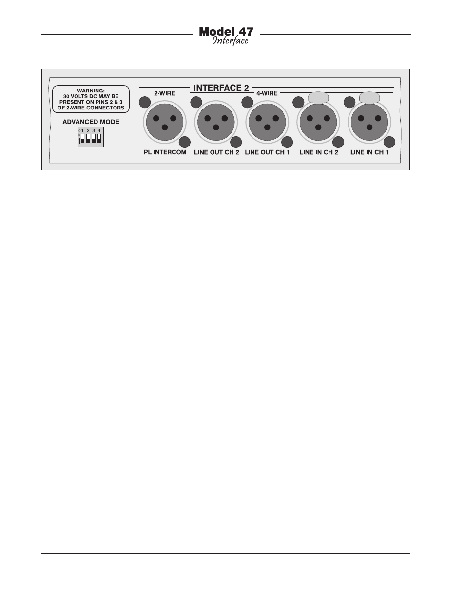
Figure 1. Detail of back panel showing line inputs and outputs