Remote control inputs – Studio Technologies 47 User Manual
Page 13
Model 47 User Guide
Issue 1, August 2010
Studio Technologies, Inc.
Page 13
Single-Channel Intercom Systems
There are two ways of connecting to the
Model 47’s 2-wire PL intercom connectors
when compatibility with Clear-Com single-
channel intercom devices is desired. The
most direct method is to prepare the fe-
male XLR mating connector so that com-
mon is on pin 1, power is on pin 2, and
audio is connected on pin 3. With this con-
nection scenario only audio channel two,
associated with pin 3 of the Model 47’s
2-wire PL intercom interface connectors
will be utilized. Pin 2, the Model 47’s audio
channel 1, will only be used for connecting
DC power to the connected devices.
In some single-channel PL intercom sys-
tem applications it may be desirable to take
full advantage of the two channels associ-
ated with each Model 47 interface. In these
applications one might want to view the
Model 47 as providing four 2-wire-to-4-wire
interface circuits. The Model 47 can cer-
tainly be used in this fashion, but adapter
cables will have to be prepared. Refer to
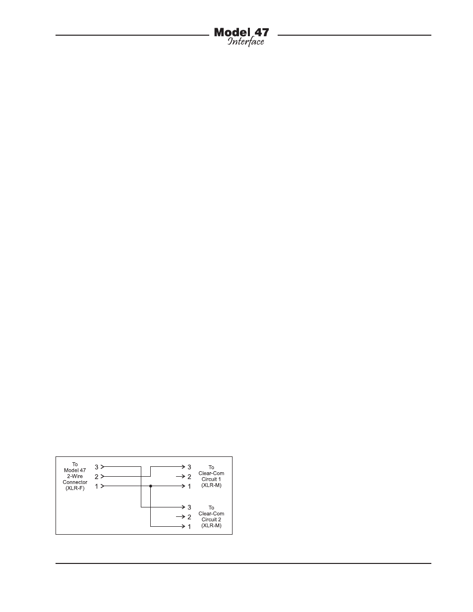
Figure 2 for details.
These adapters will “split” the Model 47’s
2-wire PL intercom connectors into two
3-pin male XLR connectors, one for each
audio channel. Pin 1 of the female 3-pin
XLR intended to mate with the Model 47
will connect to pin 1 of both 3-pin male
XLR connectors. Pin 2 of the female XLR
will go to pin 3 of the male XLR designated
as channel 1. Pin 3 of the female XLR will
go to pin 3 of the male XLR designated as
channel 2.
Using two adapter cables the Model 47
can be directly interconnected with four
Clear-Com intercom circuits. However,
power for the connected devices must
be provided by external power sources.
The Model 47’s ability to supply intercom
power will not be utilized.
Note: It’s critical that the correct con-
figuration settings be made when using
the Model 47’s interfaces to support four
independent intercom circuits. Specifically,
the 2-wire power source configuration DIP
switches must be set for external. In addi-
tion the auto terminate DIP switch must be
placed in its on (up) position. Refer to the
Configuration and Advanced Configura-
tion sections of this user guide for details.
Remote Control Inputs
The Model 47 allows connection of three
externally provided DC signals. These
signals can provide remote control opera-
tion of three functions: auto nulling for
interface 1, auto nulling for interface 2, and
a special “mic kill” function. Remote con-
trol of the auto nulling functions provides a
resource identical to that of the front-panel
pushbutton switches. The exact manner in
which the buttons and the remote control
inputs operate depends on the setting
of the auto null button configuration DIP
switch. The “mic kill” function is unique,
only being available using the remote
control input. It causes a 500 millisecond
“burst” of 24 kHz signal to be sent se-
quentially to both of the 2-wire partly-line
interface channels associated with each
of the Model 47’s two interfaces. To clarify,
a “mic kill” signal is sent to a total of four
Figure 2. Adapter cable wiring diagram