Auto terminate – Studio Technologies 47 User Manual
Page 18
Issue 1, August 2010
Model 47 User Guide
Page 18
Studio Technologies, Inc.
Auto Terminate
The auto terminate function is designed to
ensure that each 2-wire-to-4-wire interface
circuit remains stable under most oper-
ating conditions. Specifically, 200 ohm
impedances are automatically applied to
both pins 2 and 3 of a Model 47 2-wire
party-line interface when that interface is
configured for external power and no ex-
ternal source of intercom power is detect-
ed on pins 2 or 3. This function is directly
compatible with RTS TW-series intercom
applications in which the three conductors
of a cable support both DC power and two
channels of audio. It’s also compatible in
situations where all three conductors of a
Clear-Com single-channel intercom circuit
are connected to the Model 47. In this lat-
ter case only one of the Model 47’s audio
channels will be used.
There may be situations where it’s neces-
sary for the two channels associated with
each Model 47 interface be used with
separate 2-wire party-line circuits. An ex-
ample of this might be where two “loops”
of single-channel belt packs, such as units
from Clear-Com, need to be connected.
Adapter cables as shown in Figure 2
would be used. In this case the intercom
circuit’s DC power will not be connected
to the Model 47, but only to the user
devices. In this scenario, a DC voltage
won’t be present on pins 2 or 3. Another
example of this might be where adapter
boxes with DC blocking are used to inter-
connect intercom circuits with the Model
47. In both these cases a DC voltage
won’t be present on either pins 2 or 3 and
the Model 47 will automatically apply 200
ohm terminations. In both these cases the
termination will be in error and will result in
incorrect audio levels due a double-termi-
nation condition.
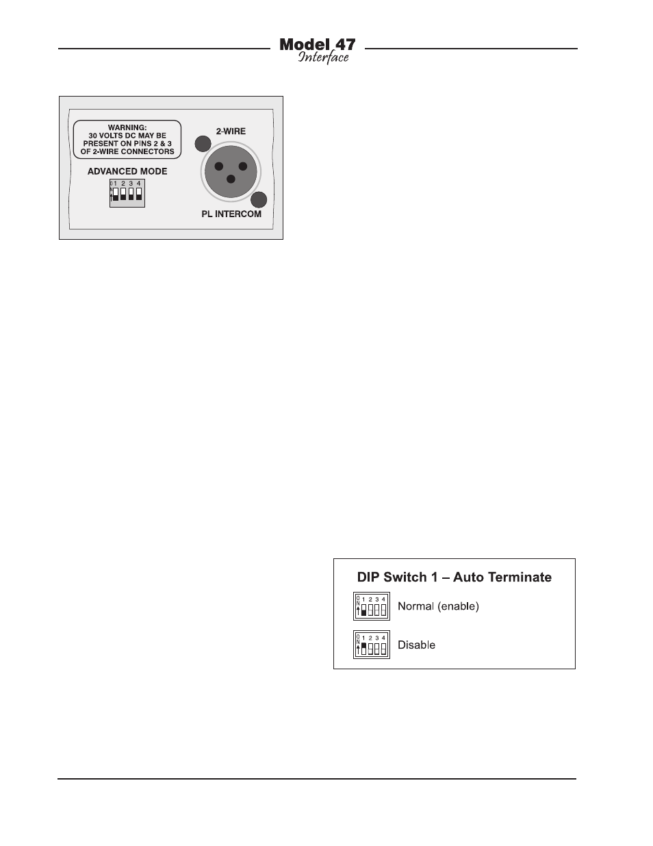
To prevent this problem the auto termi-
nate function can be disabled. Referring
to Figure 7, when DIP switch 1 is in its off
(down) position the auto terminate func-
tion is active. When DIP switch 1 is in its
on (up) position the auto terminate func-
tion is disabled. Repeating for clarity, the
auto terminate function applies to both
interfaces 1 and 2. With the auto terminate
function disabled the two interfaces, when
set for external power, will operate nor-
mally with the exception that pins 2 and 3
will never be terminated by the Model 47’s
circuitry.
Figure 6. Detail of back panel showing the
Advanced Mode DIP switches
Figure 7. DIP Switch 1—Auto Terminate