Auto null – Studio Technologies 47 User Manual
Page 24
Issue 1, August 2010
Model 47 User Guide
Page 24
Studio Technologies, Inc.
devices to stabilize. The LEDs associated
with pins 2 and 3 will light to indicate that
the outputs are active. After this initial
3-second period monitoring becomes
active. A fault condition is detected if
the power on a pin falls below 24 volts
for a continuous 1-second interval. The
hardware and software responds to this
condition by turning off the power source
on that specific pin and flashing its associ-
ated LED as a warning. After a 5-second
“cool down” interval the output returns to
the same condition as upon initial power-
up: power is again applied to the pin, the
pin status LED will light, and monitoring
won’t begin for another three seconds. A
full short-circuit condition applied to the
Model 47’s 2-wire connectors will result
in a continuous cycle of four seconds on
(three seconds for start up and one sec-
ond for detection) and five seconds off.
Auto Null
Each of the Model 47’s dual-channel inter-
faces has circuitry to automatically null the
two 2-wire-to-4-wire interfaces. Normally
this process is performed at the time of
initial Model 47 configuration but there’s
no reason why auto nulling can’t be initiat-
ed anytime one desires. The only time that
auto null must be performed is if condi-
tions have changed vis-à-vis the intercom
user devices and wiring connected to a
Model 47 2-wire PL interface connector.
Even a slight change to an intercom cir-
cuit, such as adding or removing a section
of cable, is sufficient to require that the
auto null process be performed.
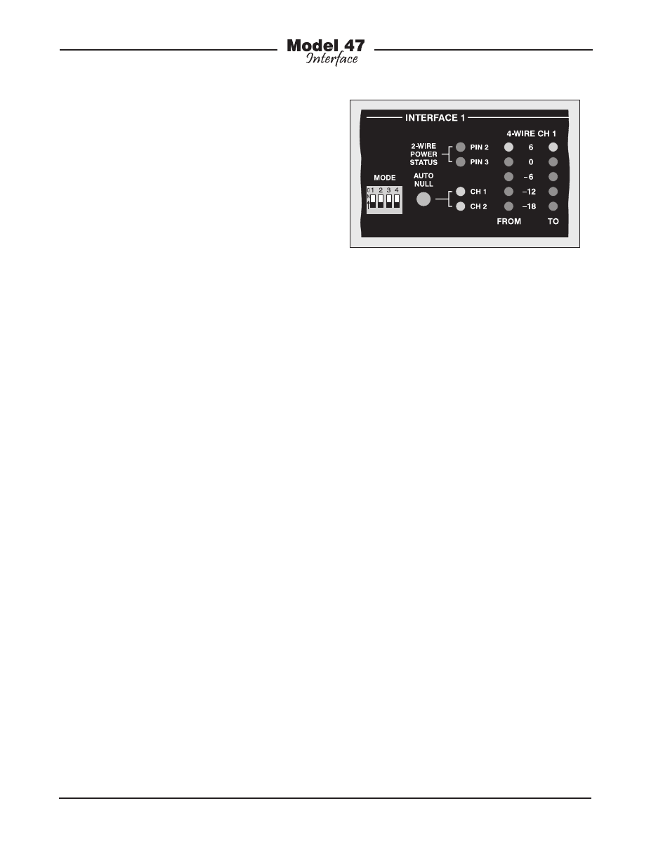
Two buttons, one associated with each
interface, are provided to activate the
auto null process. Refer to Figure 11
for a detailed view. To initiate auto null
simply requires tapping (pressing and
releasing) a button. The process begins
by nulling channel 1 of an interface and,
when completed, moves on to channel 2.
Two LEDs provide a visual indication of
the auto null process, flashing when the
auto null process for its respective chan-
nel is active.
An actual auto null sequence starts by
muting the 4-wire input and output signal
paths associated with the specific channel
to be nulled. Then a short period of 24 kHz
signal is sent out the 2-wire PL intercom
interface channel. This will turn off micro-
phones on those connected user devices
that are compatible with the RTS TW-
series “mic kill” protocol. The actual auto
nulling process will next be performed. A
series of tones will be sent out the 2-wire
interface. Other Model 47 circuitry, un-
der software control, will rapidly perform
adjustments to achieve the best null pos-
sible. After the adjustments are made the
results are stored in non-volatile memory.
Once the process has completed the
4-wire input and output paths are again
activated.
Advanced configuration DIP switch 2,
located on the back panel, allows an
independent auto null button mode to be
Figure 11. Detail of front panel showing auto
null section