Configuration, Configuration, Mounting – Studio Technologies 5152 V.2 User Manual
Page 14: Rs-485 address
Issue 4, September 2013
Model 5152 User Guide
Page 14
Studio Technologies, Inc.
Model 5152
Video Generator/Audio Embedder Module
drop of about 2 volts when active. This will
result in a GPO output current of approxi-
mately 9 milliamperes. This LED current
will be perfectively satisfactory in many
applications but many contemporary LEDs
can function effectively with less current.
Adding additional series resistance can re-
duce the output current. For example, add-
ing 100 ohms in series with the GPO will
reduce the current through a typical LED
to about 5 milliamperes. Note that shorting
pin 3 to pin 1 when the GPO is active will
result in a current flow of approximately 22
milliamperes. While this situation is not rec-
ommended it won’t lead to any damage to
the Model 5152’s circuitry.
Mounting
The Model 5152 is intended for mount-
ing in an installation-specific enclosure or
rack panel. Refer to Appendix C at the end
of this guide for details on the required
mounting opening and screw locations.
Please contact the factory to discuss
mounting options.
Configuration
The manner in which a specific Model
5152 operates depends on how it has
been configured. One configuration param-
eter, RS-485 Address, is set in hardware
using four DIP switches. The other Model
5152 operating parameters can be set
either by way of menu pages associated
with a Model 5190 Remote Access Module
or by way of a simple text file that is stored
on a USB flash drive. (The file will auto-
matically load when the USB flash drive is
inserted into the Model 5152.) To assist in
the configuration process an information
file, STATUS.TXT, is automatically created
by the Model 5152 and stored on the same
USB flash drive.
Note that there are a number of unused
DIP switches. One is located on the MCU
board and five are located on the FPGA
board. These switches are reserved for
future use.
1. Common
2. GPI (general-purpose input)
3. GPO (general-purpose output)
Figure 5. GPI and GPO Connections
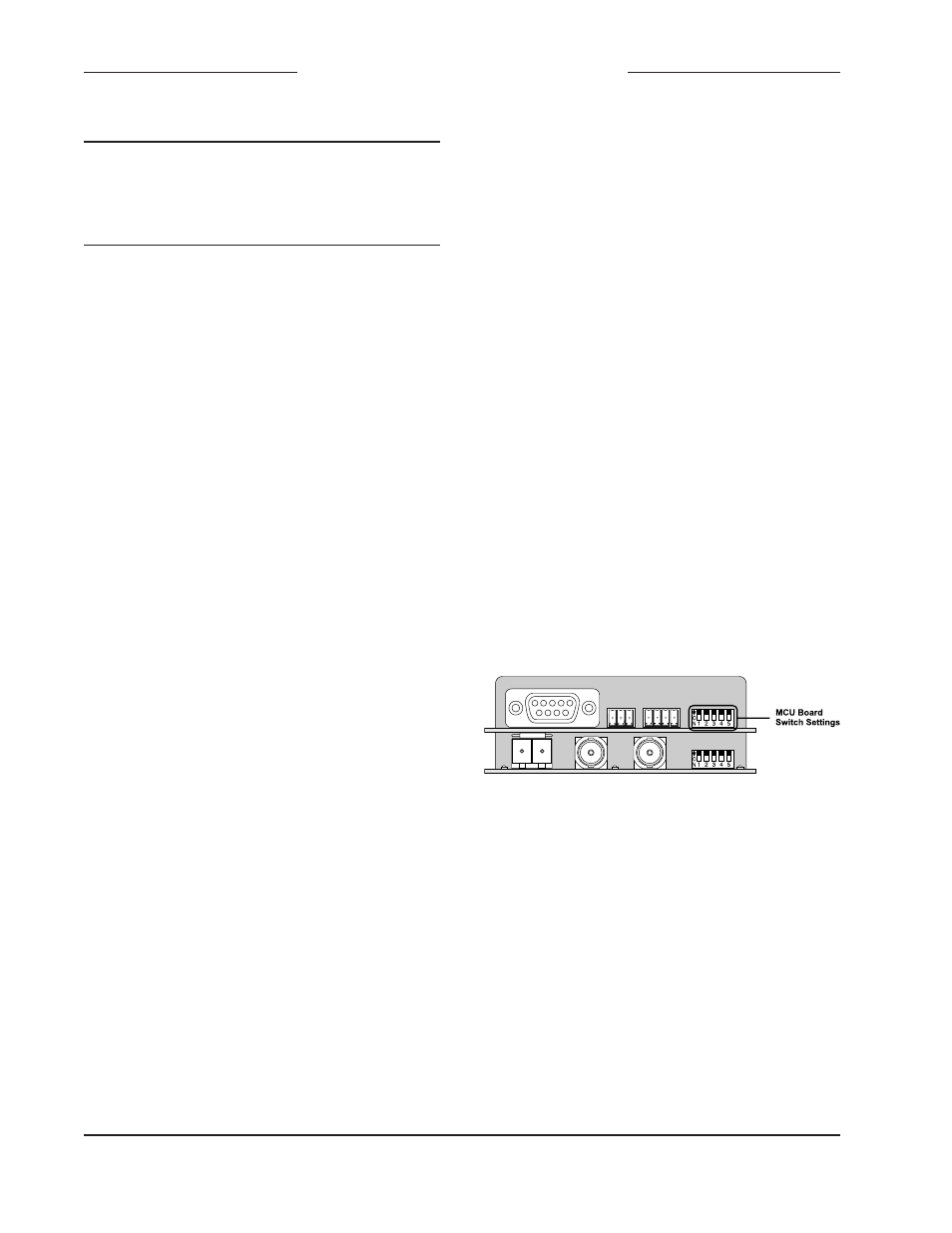
Figure 6. Rear view of Model 5152 showing
MCU board configuration switches
RS-485 Address
A data bus address must be configured
for applications that implement remote
control of Model 5152 functions. While up
to 16 Model 5100-Series modules can
“share” the RS-485 data bus, each module
must have a unique address. Selecting the
device’s address involves setting four con-
figuration switches on the MCU board. The
switches are a “piano key” type with their
up position being defined as off and their
down position defined as on.