Technical notes, Multi-unit data bus interconnection – Studio Technologies 240 User Manual
Page 24
Issue 1, August 2013
Model 240 User Guide
Page 24
Studio Technologies, Inc.
intercom sidetone trim pots to their fully
counterclockwise positions. This will mini-
mize the increase in sidetone level that will
occur when both the main sidetone and the
sidetone associated with main output-to-
intercom functions are active.
Technical Notes
Multi-Unit Data Bus
Interconnection
To interconnect the data bus signals on two
Model 240 units requires just one pair of
interconnecting wires. This provides a se-
rial data path, technically an RS-485 data
circuit with the specific characteristics of
115.2 kbps, 8-1-N. If shielded cable is to be
utilized the shield connection should only be
terminated at one end. If it’s terminated at
both ends a connection between the com-
mon points in both Model 240 units will be
established which can lead to audio noise
issues, especially when intercom circuits
are also being connected.
The data bus is accessible by way of a
3-pin “header” located on the Model 240’s
circuit board. The installer must provide the
desired connector and mount it in one of the
four spare connector locations on the back
panel. The type of connector can range from
a 3- or 4-pin XLR to one pair on an RJ-45,
such as provided by an EtherCon® connec-
tor. A simple means of providing access to
the data bus is to use the Studio Technolo-
gies EtherCon Connector Card Kit (part
number 31207). It’s very simple to install
and includes a pre-terminated interconnect-
ing cable. A standard Ethernet patch cable
would then be used to interconnect the two
Model 240 units. Refer to Appendix B at the
end of this guide for connection details.
inputs. Adjusting them is very simple, requir-
ing only a pair of ears and a screwdriver.
With the Model 240 configured as previ-
ously described, activate one of the main
output-to-intercom functions. When the talk
button associated with the configured chan-
nel is activated audio from the connected
headset microphone may be heard in the
configured headphone output channel(s).
Adjust the trim pot associated with the active
intercom channel so that the desired side-
tone level, relative to the intercom receive
level, is achieved. The adjustment range is
approximately 18 dB, with the sidetone level
increasing as the trim pot is rotated in its
clockwise direction. Now change to the other
intercom channel and adjust its sidetone trim
pot as desired.
Using the Model 240’s main sidetone func-
tion, talk audio can be routed to the head-
phone outputs by means of active circuitry.
If this is enabled be certain to place the two
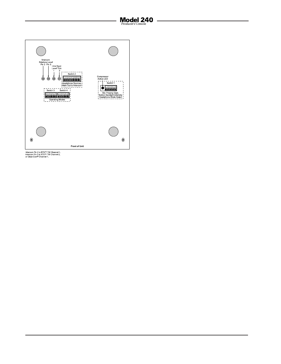
Figure 17. Bottom view showing line input and
intercom sidetone trim pots