Headphone stereo/mono, Main output to intercom functions – Studio Technologies 240 User Manual
Page 17
Model 240 User Guide
Issue 1, August 2013
Studio Technologies, Inc.
Page 17
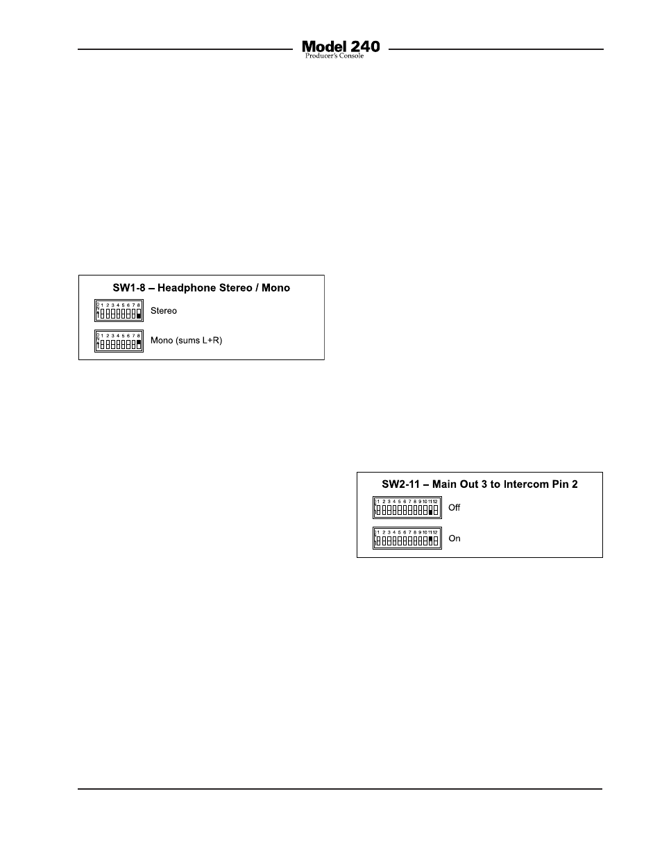
Headphone Stereo/Mono
Switch SW1-8 allows a monaural head-
phone output to be created. This is accom-
plished by summing (adding) the selected
left- and right-channel audio sources. When
SW1-8 is enabled, the signals are sent to
both the left- and right-channel headphone
output driver circuits. The outputs of these
circuits connect, by way of 100 ohm series
protection resistors, to the headphone out-
put pins of the headset connector.
phone output’s left channel will also be pres-
ent on the right channel. A stereo headphone
mix can’t be created. But in most cases this
limitation won’t overshadow the benefit of
being able to create a mix. For signal-flow
clarification please review the block diagram
located at the end of this guide.
Main Output to Intercom
Functions
The last two switches in switch assembly
SW2, SW2-11 and SW2-12, are used to
configure the routing of audio associated
with the main outputs. SW2-11, when en-
abled, routes audio associated with main
output 3 to intercom interface pin 2. SW2-12
allows audio associated with main output 4
to be routed intercom interface pin 3.
Main Output 3 to Intercom Pin 2 Function
Mode
Switch SW2-11 configures whether the audio
signal associated with main output 3 will be
routed to pin 2 of the intercom interface.
Figure 9. Main output 3 to intercom pin 2
settings
Two modes are available:
• Off: In this mode audio will not be routed
to pin 2 of the intercom interface.
• On: In this mode audio associated with
main output 3 will be routed to pin 2 of
the intercom interface. (Note that pin 2
is channel 1 of an RTS TW intercom sys-
tem. For typical single-channel Clear-Com
party-line intercom systems pin 2 is not
associated with an audio channel.)
Figure 8. Headphone stereo/mono settings
The headphone stereo/mono feature was
specifically included so that a 3-channel
monaural headphone mixer mode can be
created. By enabling headphone mono, the
three front-panel user level controls (“pots”)
can be used to create the desired “mix” of
signals being sent to the headphone out-
puts. Many applications may benefit from
this capability. The desired headphone
sources must be carefully assigned to take
advantage of the monaural feature. The first
source should be assigned, using the DIP
switches, to the left channel. Its output level
will be adjusted by the control on the far
left. The second source should be assigned
to the right channel. Its output level will be
adjusted by the center control. A third cue
signal, sidetone, can also be enabled. The
side-tone level control, located on the far
right, will be used to adjust its level.
There is one limitation related to the head-
phone output mono feature. It’s the fact
that the output will be 2-channel monaural.
Whatever signal is present on the head-