Operation, Conclusion – Studio Technologies 240 User Manual
Page 20
Issue 1, August 2013
Model 240 User Guide
Page 20
Studio Technologies, Inc.
Four choices are available for each main
output:
• Off: No program audio is routed to the
associated main output.
• On, Mutes during Talk: Program audio is
routed to the associated main output but
mutes (fully attenuates) whenever talk
audio is actively being sent to that main
output.
• On, Dims (attenuates 15 dB) during Talk:
Program audio is routed to the associ-
ated main output but reduces in level
(“dims”, i.e., attenuates by 15 dB) when-
ever talk audio is actively being sent to
that main output.
• Always On: Program audio is routed to
the associated main output and remains
at full level, whether or not talk audio is
actively being sent to that main output.
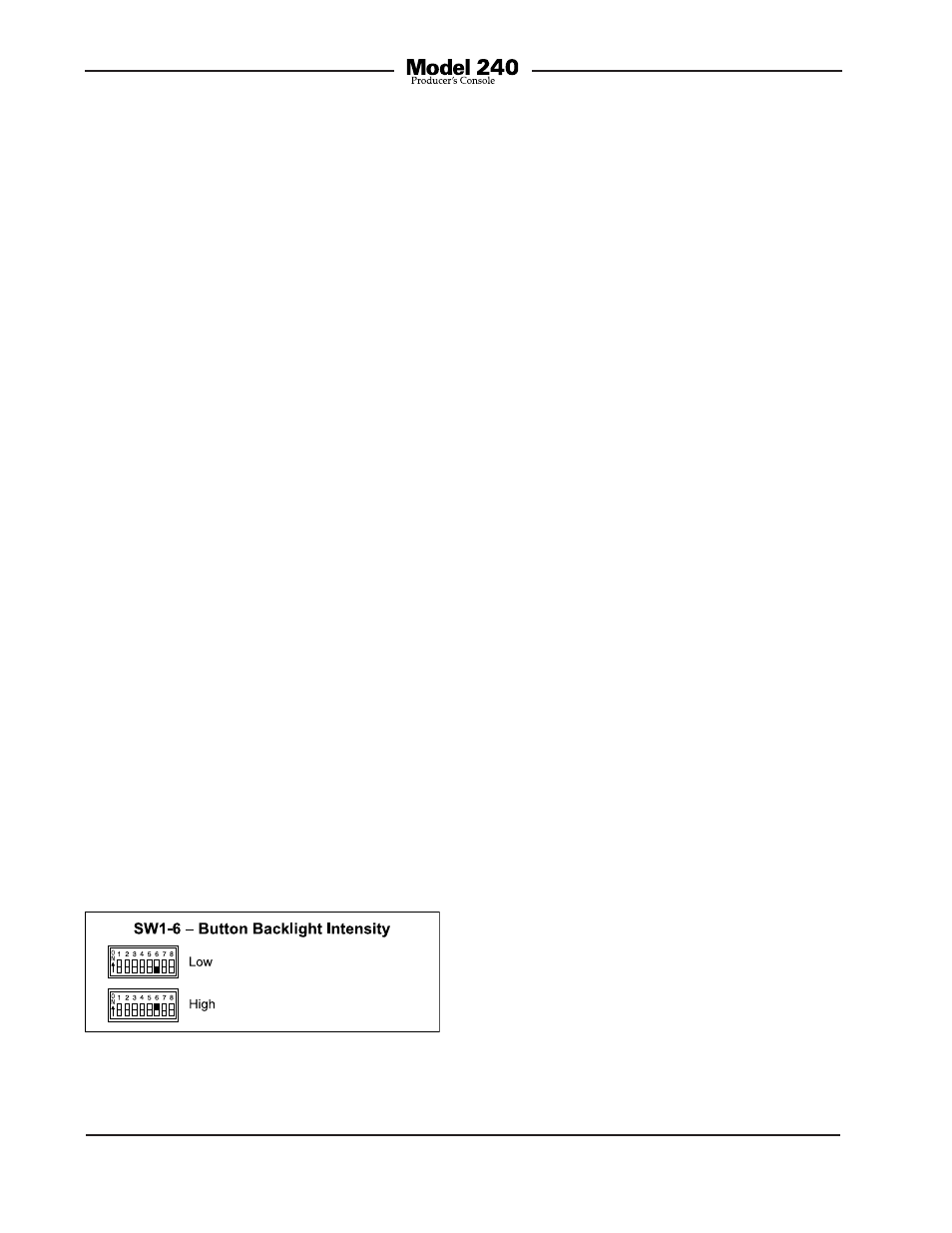
Button Backlight Intensity
Switch SW1-6 selects the intensity of the
white LEDs that provide backlighting for
the four pushbutton switches. Two choices
are available: low and high. Low is appro-
priate when the Model 240 is going to be
used in an environment where the ambient
light level is low. High would be appropriate
where other light sources in the physical
area may make the buttons more difficult
to identify. High may also be useful when
identification markings have been inserted
under the clear lens caps.
Conclusion
Once the switches have been set to the de-
sired Model 240’s operating configurations,
it may be time to reattach the security plate.
The exception is if the trim pots associated
with the line inputs and intercom sidetone
(null) need to be adjusted. Details are pro-
vided later in this guide. The plate attaches
using the four rubber bumpers. They should
be hand-tightened only; no tools are to be
used.
Operation
At this point the desired input, output,
and power connections should have been
made. The buttons may have had labels
installed. After carefully reviewing the needs
of the specific application, the configura-
tion switches should have been set. Normal
operation of the Model 240 can now begin.
The unit will begin functioning as soon as
a power source is connected. As previously
discussed, power for the Model 240 can
be provided by an external source of 24
volt DC or a connected party-line intercom
circuit. It’s important to highlight the fact that
the Model 240 is an active device. Audio sig-
nals will not be present on the main outputs,
headphone output, or intercom interface un-
less a power source has been connected.
Upon Model 240 power up the unit’s firm-
ware will “boot” (start up) and the eight
LEDs (four white LEDs that provide back
lighting for the four pushbuttons and four
green status LEDs associated with the main
output functions) will light in a sequence.
The unit will then begin normal operation.
The user is now presented with four but-
tons and associated LEDs and three rotary
controls. These are simple to operate and
understand, as will be described in the
following paragraphs.
Figure 16. Button backlight intensity settings