Headphone source selection – Studio Technologies 240 User Manual
Page 15
Model 240 User Guide
Issue 1, August 2013
Studio Technologies, Inc.
Page 15
input source the 0 dB setting would never
be appropriate. The issue is that with no
gain added to the microphone input signal,
the relative noise floor on the main outputs
would be much too high. And the relative
level of the talk signal versus a program or
intercom input signal would be completely
mismatched.
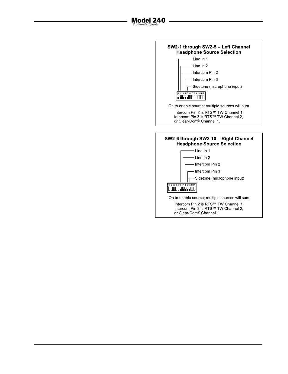
Headphone Source Selection
The first ten switches associated with
switch assembly SW2 are used to con-
figure the sources that are routed to the
headphone output. Five headphone
sources are available: line input 1, line
input 2, intercom pin 2, intercom pin 3,
and sidetone. Each of these sources can
be independently assigned to the left,
right, or both the left and right channels
of the stereo headphone output.
As previously noted, two line-level input
sources are interfaced using two connec-
tors located on the back panel. Associ-
ated with line inputs 1 and 2 are level trim
potentiometers. They are provided so that
audio sources with a wide range of nomi-
nal levels can be effectively used as cue
sources. Please refer to the Advanced
Operation section of this guide for details
on using the trim pots.
Audio associated with the two channels
of party-line intercom, referred to as pin 2
and pin 3, is provided by way of the in-
tercom interface whose connector is also
located on the back panel. With broad-
cast-standard RTS TW party-line intercom
systems pin 2 is audio channel 1; pin 3
is audio channel 2. With the ubiquitous
Clear-Com single-channel party-line sys-
tems pin 2 contains only DC power and
no audio; pin 3 provides the one (and only)
audio channel. Two trim pots are associ-
ated with the intercom channels. They
allow adjustment of the intercom sidetone
(null) level of the actual intercom inter-
face circuitry. This impacts the amount
of main output (talk and, if selected, pro-
gram) audio signal that is returned to the
headphone output when intercom audio is
selected for monitoring by the headphone
output and either or both of the main out-
put-to-intercom functions are active.
The switches designated for the sidetone
audio source select audio that comes from
the output of the compressor circuit as-
sociated with the microphone preamplifier.
This allows a producer or other Model 240
Figure 6. Left and right channel headphone
source selection settings