Restore factory defaults, Model 71 control console configuration – Studio Technologies 76DBA V.3.00 User Manual
Page 26
Issue 1, November 2010
Model 76DBA/77B User Guide
Page 26
Studio Technologies, Inc.
for Surround
Restore Factory Defaults
The restore factory defaults function is pro-
vided primarily for factory use. In this way
a system can be shipped with the default
settings selected. While you are welcome
to use this function, be careful so that your
configuration efforts aren’t wasted. Spe-
cifically, be aware that the reference level
is reset to minimum level. All the other
parameters are fairly easy to set up, but
resetting the reference level would require
getting out an SPL meter and a calibrated
signal source. This is a hassle you may not
need!
Model 71 Control Console
Configuration
The only configuration choice available on
a Model 71 is its device address. It must
be selected so as not to conflict with the
device address of any other connected
Model 71 or Model 77B Control Console.
The choices are A1, A2, A3, and A4. All
Model 71 units have a default device ad-
dress of A4; Model 77B’s units have a
default device address of A1. This ensures
that, in most cases, no change will have
to be made. Refer to Figures 8 and 9 for
details.
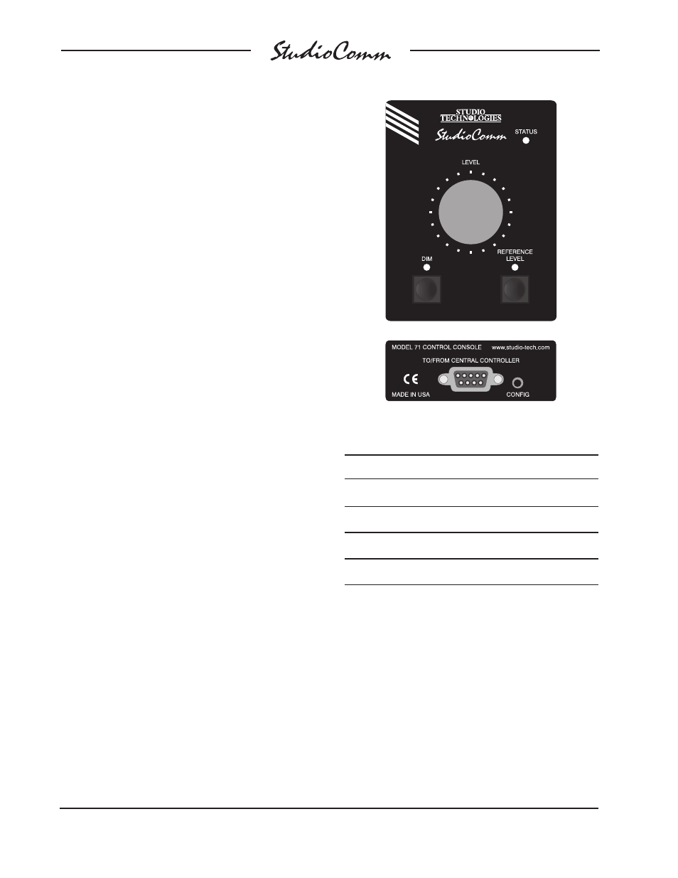
A small button is located on the back of
each Model 71 Control Console, adjacent
to the 9-pin D-sub connector. Pressing and
holding this button for two seconds places
this specific unit in its configuration mode;
normal operation of the Model 76DBA and
other connected Model 71 and Model 77B
units will continue. When a Model 71 en-
ters its configuration mode its three LEDs
will no longer perform their usual functions.
Instead the status LED will blink to indi-
cate that configuration mode is active. The
dim and reference level LEDs will display
the Model 71’s current device address.
The rotary level control is used to select
the desired device address; the LEDs will
respond accordingly.
To leave the configuration mode and return
a Model 71 to normal operation requires
one last action; again press and hold its
configure button for two seconds. The
selected device address will be stored in a
nonvolatile memory device that is located
inside this specific Model 71.
Figure 8. Model 71 Control Console Front and
Back Panels
Address
Dim LED
Reference Level LED
A1
OFF
OFF
A2
OFF
ON
A3
ON
OFF
A4
ON
ON
Figure 9. Model 71 Device Address Chart