Operation, Model 71 control console configuration – Studio Technologies 76D V.2.02 User Manual
Page 31
Model 76D/77 User Guide
Issue 2, June 2009
Studio Technologies, Inc.
Page 31
for Surround
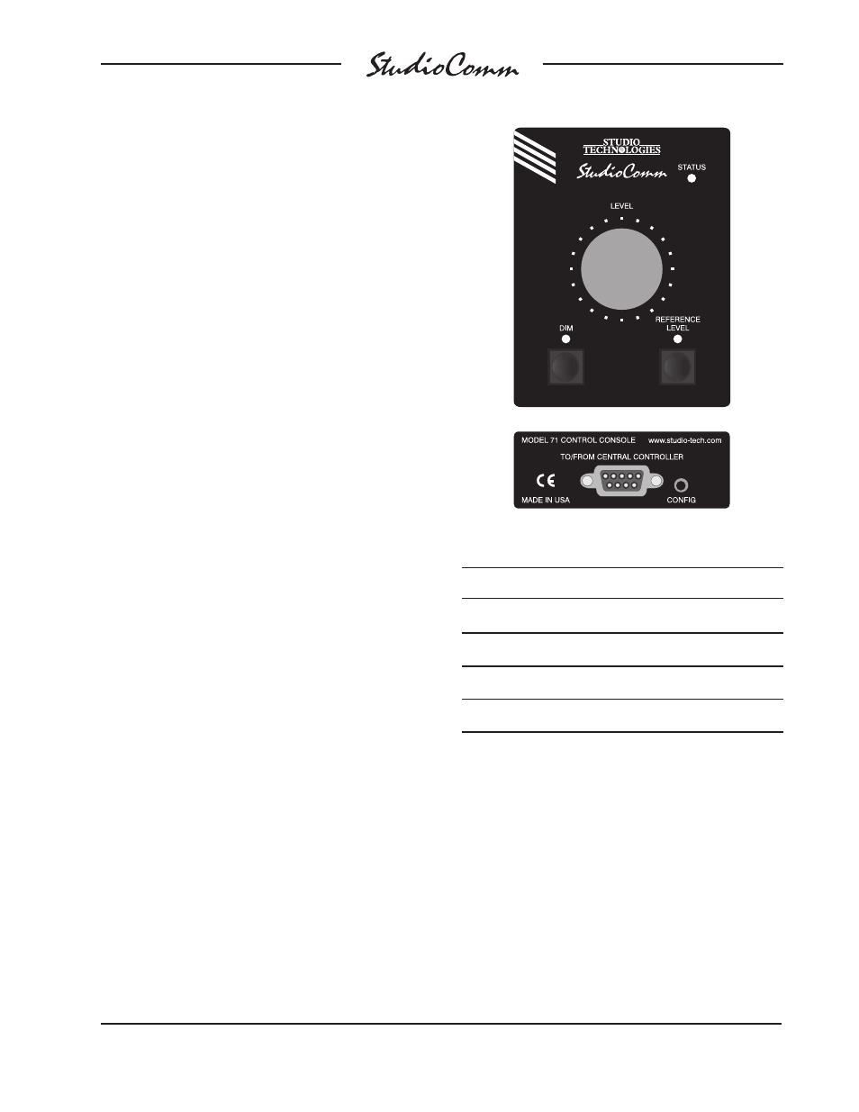
Model 71 Control Console
Configuration
The only configuration choice available on
a Model 71 is its device address. It must
be selected so as not to conflict with the
device address of any other connected
Model 71 or Model 77 Control Console.
The choices are A1, A2, A3, and A4. All
Model 71 units have a default device ad-
dress of A4 while the Model 77’s have a
default device address of A1. This ensures
that, in most cases, no change will have to
be made.
A small button is located on the back of
each Model 71 Control Console, adjacent
to the 9-pin D-sub connector. On any con-
nected Model 71 pressing and holding this
button for two seconds places this spe-
cific unit in its configuration mode; normal
operation of the Model 76D and other
connected Model 71 and Model 77 units
will continue. When a Model 71 enters its
configuration mode its three LEDs will no
longer perform their usual functions. In-
stead the status LED will blink to indicate
that configuration mode is active. The dim
and reference level LEDs will display the
Model 71’s current device address. The
rotary level control is used to select the
desired device address; the LEDs will
respond accordingly. Refer to Figures 7
and 8 for details.
To leave the configuration mode and return
a Model 71 to normal operation requires
one last action; again press and hold its
configure button for two seconds. The
selected device address will be stored in
a nonvolatile memory device that is located
inside this specific Model 71.
Operation
Now that you’ve installed and configured
the system, you’re ready to go. You should
find operation very easy. However, taking
time to study this section of the guide may
prove valuable.
Address
Dim LED
Reference Level LED
A1
OFF
OFF
A2
OFF
ON
A3
ON
OFF
A4
ON
ON
Figure 8. Model 71 Device Address Chart
Figure 7. Model 71 Control Console Front and
Back Panels