Delta Electronics EME-A22A User Manual
Eme-a22a, Layout, Installation
2007-07-09
5011659501-AAT1
EME-A22A
Analog Extension Card for VFD-E Series Instruction Sheet
Please thoroughly read this instruction sheet before installing option cards and putting them into use.
The content of this instruction sheet may be revised without prior notice. Please consult our distributors or download the
most updated version at http://www.delta.com.tw/industrialautomation/.
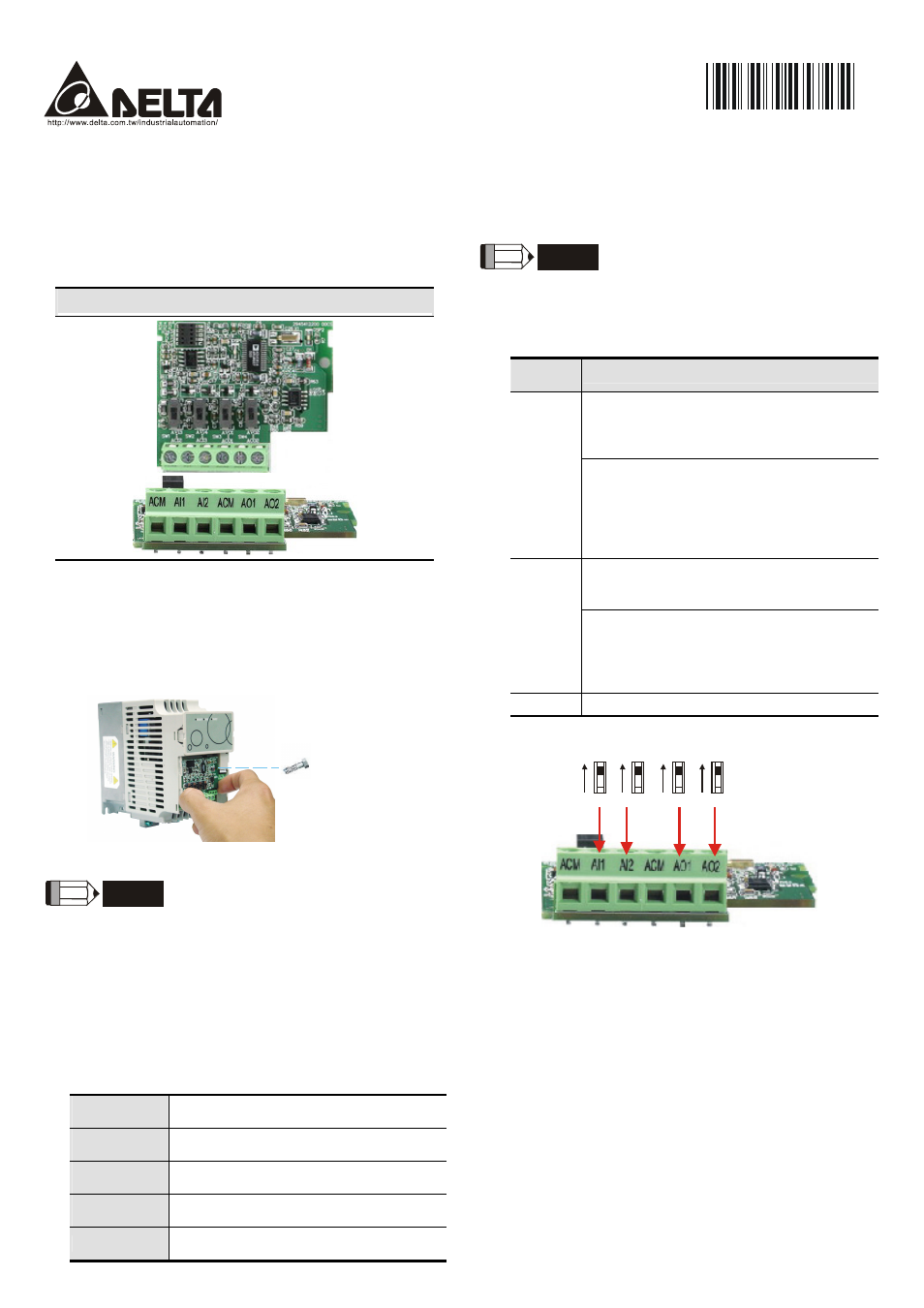
Layout
I/O Card (EME-A22A)
Installation
Make sure that the AC Motor Drive is powered off before
operation. DO NOT insert or remove the card when the AC
Motor Drive is powered on.
Please mount the extension card as shown and fix it with
the screw packed with the card.
Screw torque:
Maximum 2kgf-cm
Terminals Screw Torque: Maximum 5kgf-cm
Wire Gauge: 14 ~ 24 AWG (2.1 ~ 0.2 mm
2
)
NOTE
Only when the extension card is correctly installed on
the AC Motor Drive, the extension card will be
automatically detected. The parameters can be set in
Group 12. If extension card is not installed, only
parameters Group 0 ~ Group 10 can be set. Refer to
Chapter 5: Parameters in the user manual for further
details.
Specification
Environmental
Operating
Temperature
-10
o
C to 50
o
C (non-condensing and not
frozen)
Storage
Temperature
-20
o
C to + 60
o
C
Ambient
Humidity
Less than 90%RH (non-condensing)
Installation
Altitude
Below 1000m
Vibration
Below 20 Hz: Maximum 9.81 m/s
2
(1G)
20 ~ 50Hz: Maximum 5.88 m/s
2
(0.6G)
NOTE
Always use this product in a clean indoor location free
from dust, corrosive gas and liquid.
Inputs/Outputs
EME-D33A
Terminal
Symbols
Descriptions
Input Voltage: 0 ~ 10VDC =0 ~ Maximum
Output Frequency (Pr.01.00)
Input Impedance: 100KΩ
Resolution: 12 bits
AI1
AI2
Input Current: DC 0 ~ 20mA=0 ~ Maximum
Output Frequency (Pr.01.00)
Input Impedance: 250Ω
Resolution: 12 bits
Voltage/Current Switch: Please refer to the
following diagram
Output Voltage: DC 0 ~ 10V
Output Impedance: 1K ~ 2MΩ
Resolution: 12 bits
AO1
AO2
Output Current: DC 0 ~ 20mA
Output Impedance: 0 ~ 500Ω
Resolution: 12 bits
Voltage/Current Switch: Please refer to the
following diagram
ACM
Analog control signal common
Voltage/Current Switch
AVI3
ACI2
AVI4
ACI3
AVO1
ACO1
AVO2
ACO2
Notes
When the relays are used to switch inductive loads (relays,
contactors, motors, etc), connect an RC network or Varistor
parallel to the load to suppress voltage spikes.
For safety, it is recommended to use fuses for the circuitry
that is switched by the relays. The fuse specification must
be within the specified contact limits.
Please use shielded wires to avoid interferences and
connect the shield to ground.
The ends of wires must be tinned or crimped.
To avoid interference, route the extension card wires
separately and as far away (at least 15cm) as possible from
other control wires, motor wires and power wires, etc.
Where these wires must cross each other, please make
sure they are at a 90
o
angle.
Always use and operate this product within the limit of its
specifications.