0) electrical connections, Internal connection wiring diagram, Electric shock hazard – Space Ray RSTP Series User Manual
Page 17
Form 43206000
-16-
Sept 2011
13.0)
ELECTRICAL CONNECTIONS
Failure to do so may result in death or serious injury.
This appliance must be connected to a properly grounded electrical source.
Disconnect electrical power and gas supply before servicing.
ELECTRIC SHOCK HAZARD
1.
All electric wiring shall conform to the latest edition of the National Electrical Code (ANSI/NFPA No. 70), or
the code legally authorized in the locality where the installation is made.
2.
The unit must be electrically grounded in accordance with the National Electrical Code (ANSI/NFPA No.
70-latest edition). In Canada, refer to current standard C22.1 Canadian Electrical Code Part 1.
3.
The wiring providing power to the heater shall be connected to a permanently live electrical circuit, one that
is not controlled by a light switch.
4.
The power supply to the unit should be protected with a fused disconnect switch or circuit breaker. A service
switch, as required by local codes, shall be located in the vicinity of the heater (check local codes for
allowable distances) and should be identified as Heater Service Switch. All electrical wiring must be located
in accordance with the required Clearances to Combustibles from the heater as listed on the nameplate on
the heater.
5.
When connecting the supply circuit
supply circuit
supply circuit
supply circuit to the heater, wiring material having a minimum size of 14 AWG and a
temperature rating of at least 90°C shall be used.
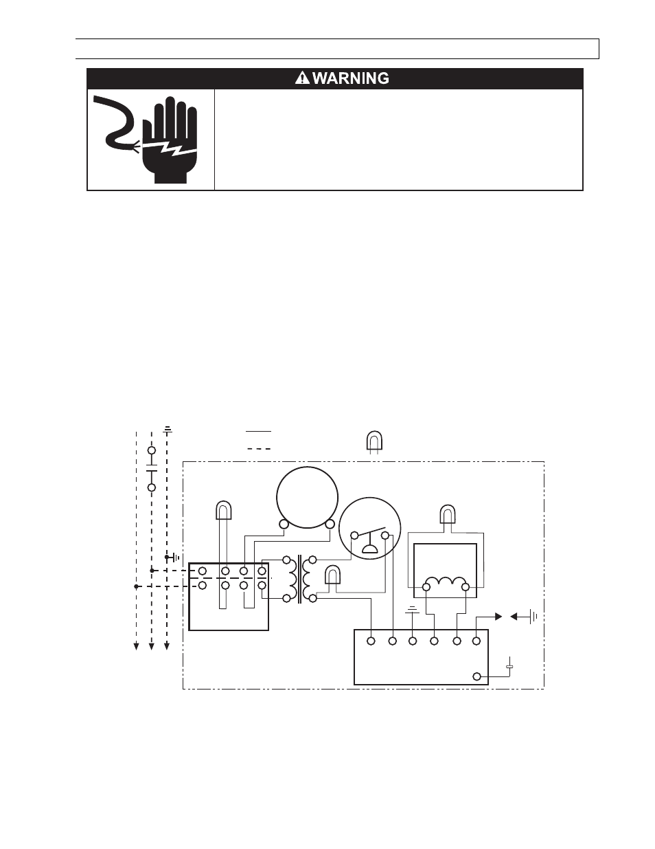
INTERNAL CONNECTION WIRING DIAGRAM
INTERNAL CONNECTION WIRING DIAGRAM
INTERNAL CONNECTION WIRING DIAGRAM
INTERNAL CONNECTION WIRING DIAGRAM —
—
—
—
Direct Spark Ignition
Direct Spark Ignition
Direct Spark Ignition
Direct Spark Ignition
FLAME
SENSOR
v
G
BL
BL
BK
BK
R
W
BK
BK
R
BK
W
BK
BK
BK
W
DRAFT
INDUCER
MOTOR
GAS VALVE
AIR SWITCH
25V
(GND)
25V GND
(BURNER)
VALVE VALVE
TRANSFORMER
120V PRIMARY
24V SECONDARY
A
G
R
IGNITION MODULE
HIGH VOLTAGE
CABLE
ELECTRODE
GAP 3/16
CONTINUE TO
ADDITIONAL
HEATERS
NEUTRAL
120V
THERMOST
A
T
GROUND
L1
L2
TERMINAL
BLOCK
FACTORY WIRING
FIELD WIRING
CONTROL CABINET
MONITORING LIGHTS
Circuit d'origine
Connexions client
Lampes témoins
Neutre
Terre
Vers les autres
radiateurs
Plaque à
bornes
Transformateur
bobine primaire 120ÊV
bobine secondaire 24ÊV
pressostat
Robinet à gaz
Écartement
d'électrode
4,7Êmm
Haute tension
Armoire de commande
Bloc d'allumage
Moteur
d'amorce
d'aspiration
NOTES:
NOTES:
NOTES:
NOTES:
1.
If any of the original wire as supplied with the appliance must be replaced, it must be replaced with wiring
material having a temperature rating of at least 105ºC. (18 Ga. CSA 600V Type TEW)
2.
When connecting the supply circuit to the heater, wiring material having a minimum size of 14 AWG and a
temperature rating of at least 90ºC shall be used.
3.
A replaceable 3-amp fuse (1-1/4” long) is fitted to the Ignition Control Module.