Viii. wiring the nrc, Ix. connecting devices on the sp bus – SP Controls PX2-NRC-1142 User Manual
Page 17
VIII. Wiring the NRC
Powering the NRC System
Power the NRC with the included wall wart power supply. All SP Bus devices (Pucks and Modular
Panels) will be powered over the Bus connection and do not require their own power supply.
Wiring the NRC to a Projector/Monitor
The NRC is usually mounted directly on the primary projector or display device. Attach the NRC to the
device with the included Velcro
TM
tape. The NRC controls the display device with its integrated RS-232
and IR outputs.
Note: The NRC IR emitter cannot be used to control a second device, even if the NRC controls the
primary projector through RS-232 alone. To control additional devices through IR, a Control Puck
must be used.
To connect the NRC IR emitter bud directly to an IR receiver window on the display device, remove
the adhesive backing from the bud and place and hold it to the window. Be careful to place the bud
immediately adjacent to the IR receiver component – some devices are sensitive to the placement of
the emitter bud.
Most display devices use a DB9 or HD15 connector for their RS-232 control port. To connect the
NRC, use one or more of the connector adapters to match the control port pinouts of the device.
When available, the SP Controls Application Notes for projectors and monitors almost always provide
control port pinouts. You can download our Application Notes at:
http://www.spcontrols.com/drivers.php
If an Application Note is not available for your device, consult its technical manual for control pinouts.
An intermediate RS-232 cable may be used for strain relief or to extend the RS-232 connection so the
NRC may be mounted elsewhere in the room. If you position the NRC in a rack and extend the RS-
232 cable, use a 3-conductor cable. The NRC TX is on pin 2, RX is on pin 3, and Ground is on pin 5.
Note: Some projectors use uncommon RS-232 ports and may require that an adapter cable be man-
ufactured or specially ordered. Be sure to check our Application Notes or the projector docu-
mentation prior to installation to verify that you can the necessary control cable termination.
Wiring the NRC to a Projector/Monitor
NRC Adapter Combinations
Low-Voltage Relays
The NRC has four integrated control relays (“Screen” and “Lift”) and two input relays (labeled
“Sense”). While they are labeled to reflect the most common use for the relays, the Screen and Lift
relays may be configured to open or close in any momentary or maintained configuration and may be
tied to any system event, such as any button press on the PX2-MP-IR or web-based interface, or sys-
tem events such as power on/off or system unlock.
No relay terminals are tied to any others. If you use multiple relays to control the same
device, you must wire the commons yourself.
The two sense ports may be used to trigger system events when an external relay is closed or
opened. For example, the sense port may be used to monitor a security loop, and the NRC config-
ured to send an alert email if the loop is broken.
Attention: The NRC relays are low voltage only. This applies for all settings and situations. All of the
relays on the board are rated at 500mA max current. Under no circumstances is high voltage to
be wired to the NRC.
IX. Connecting devices on the SP Bus
All connection between the NRC and SP Bus devices (including the PX2-MP-IR modular panel and
Control Pucks) is made by CAT5, CAT5e, or CAT6 cable. The SP Bus is a proprietary format that
does not resemble Ethernet or any other network protocol – CAT5 cable is used for ease of wiring.
Any SP Bus device may be connected by CAT5 to either of the two SP Bus RJ-45 jacks on the NRC.
The RJ-45 port labeled Ethernet is for NRC configuration and network connection; it is not used to
connect SP Bus devices.
Control Pucks provide two Bus ports for easy daisy chaining. Simply connect one Puck directly to the
NRC, and run a cable from the first Puck to the second, and so on. If necessary, SP Bus ports may be
split using an RJ-45 Y-splitter to create more SP Bus ports. A total of 15 bus devices may be con-
trolled by the NRC.
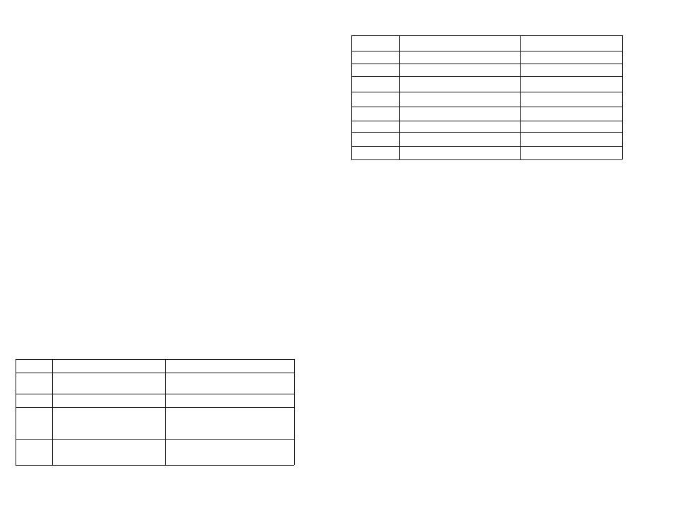
Converters
NRC Output Type/Gender
Output pinout
None
Female DB9
TX 2, RX 3, GD 5
A
Male DB9
TX 2, RX 3, GD 5
B
Female DB9
TX 3, RX 2, GD 5
A and B
Male DB9
TX 3, RX 2, GD 5
C
Male HD15
TX 14, RX 13, GD 10
C and D
Female HD15
TX 14, RX 13, GD 10
B and C
Male HD15
TX 13, RX 14, GD 10
B, C, and D
Female HD15
TX 13, RX 14, GD 10
30
Adapter
Connector Type
Description
A
DB9 male/male
Gender changer (wired straight
through)
B
DB9 male/female
Null modem
C
DB9 male/HD15 male
DB9 to HD15 adapter
(DB9 pin 2 to HD15 pin 14, 3 to 13, 5
to 10)
D
HD15 female/female
Gender changer (wired straight
through)
31