Advanced configuration - 3. attached devices – SP Controls PX2-NRC-1142 User Manual
Page 11
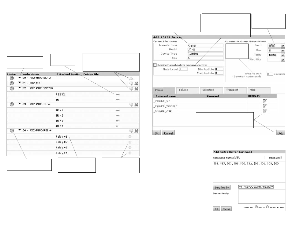
Creating a New RS-232 Driver
Add or Edit RS-232 Driver Command
This is the most important part of creating
an RS-232 driver: telling the driver what
data to send for a particular command.
First, name the command you’re creating (if
you selected the pencil icon, the name will
already have been chosen for you). The
name is how you’ll identify this command
later when you’re mapping it to a particular
button press.
The value in the box labeled Repeats tells
how many times that command will be re-
peated when it is sent. If you put “0” in this
field, the command will continue repeating
as long as the button is held.
Fill out all of the fields for the Driver
File Name (spaces and special
characters are not allowed in any
field but underscores and hypthens
are ok)
Communications param-
eters will be found with
the RS-232 specifica-
tions for your device
Some devices
require a delay
between RS-
232 commands
Complete this section for devices
with absolute volume control, i.e.
they require a specific volume level
instead of just “up” or “down”; the
min and max values will be found in
its documentation
Click on the pencil icon to edit an RS-232
command you want to associate with an
existing command name; click Add to cre-
ate an RS-232 command with a new name
19
Advanced Configuration - 3. Attached Devices
Add Nodes
The first thing you need to do is to tell the NRC if you’ll be using Control Pucks and/or a Modular
Panel. In the example we’re using, you can see that you’ll have one MP, one RS-232/IR Puck, one
IR4 Puck, and one Relay Puck. Click Add Node once for each of those nodes and select the appro-
priate device from the list each time. When you finish, you should have a screen that looks like the
image below. You can also add nodes by physically connecting devices to the NRC Bus port and an-
nouncing them on the Bus (see page 32).
Select Drivers
Each device that you’ll be controlling will be assigned to one port on one of the nodes. Click on the
“...” icon next to each port. When you do, the Select Driver File dialog box will pop open and you’ll
see a list of drivers. If you clicked on an RS-232 port, the drivers will all end with the extension
“.dev232”, and for an IR port, they’ll end with “.devir”. If you see the device you want to control on the
list, select it and click OK. If you don’t see it on the list, you’ll need to Create a New Driver.
The question mark indicate that
this node is a placeholder and is
not yet active on the SP Bus
Arrows collapse or expand
the view of the ports under
each node
An exclamation point indicates that new
firmware is available for the device on that
node, and clicking it starts the upgrade
process. Clicking the “i” inside the balloon
will show SP Bus info for that node.
Click the “...” icon
to select a driver
for that port.
Once this node is active on
the SP Bus, clicking these
dots will test the relays,
opening and closing them
Relay ports don’t get driv-
ers; relay closure actions
are configured during the
Customization step (Step 6)
18