Cv 41 f7 output location – SoundTraxx DSD-150/DSX Technical Reference User Manual
Page 33
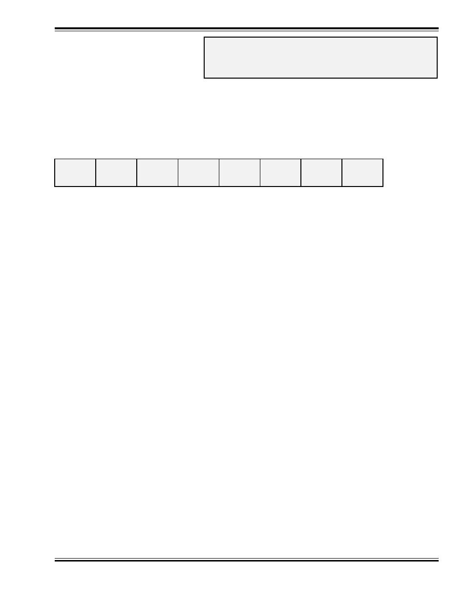
Address Mode
Direct Mode
Register Mode
Ops Mode Short Form
Paged Mode
Ops Mode Long Form
Digital Sound Decoder Technical Reference
33
CV 41
F7 OUTPUT
LOCATION
Description
Maps the F7 function to any of eight DSD auxiliary function outputs as defined by a 1 in the
corresponding bit position:
bit 7
bit 0
MUTE
CPLR
DYNO
F5
Bit 0:
F5, Function 5 Output
0 = Output is unaffected by F7.
1 = Output is activated when F7 is on.
Bit 1:
DYNO, Dynamo Sound Effect
0 = Sound is unaffected by F7.
1 = Sound is activated when F7 is on.
Bit 2:
CPLR, Coupler Sound Effect
0 = Sound is unaffected by F7.
1 = Sound is activated when F7 is on.
Bit 3:
Reserved
Bit 4:
Reserved
Bit 5:
Reserved
Bit 6:
Reserved
Bit 7:
MUTE, Audio Mute Function
0 = Sound is unaffected by F7.
1 = Sound is muted when F7 is on.
A value of 00 sets F7 to control the COUPLER sound effect.
Default Value:
4
Related CVs:
See also CVs 33-42.
❐
■
❐
❐
■
■