Another example of configuration – SONOSAX SX-62R Quick_Start User Manual
Page 5
SONOSAX SX62R
Quick Start Guide
Page 5 of 34
Another example of configuration
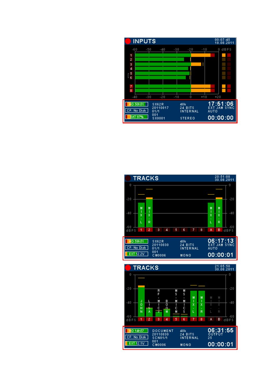
Inputs modulometers
1 to 6 are brightened = input channels are powered ON
Red square dots dimmed = input channels are not
routed (will not be recorded)
Faders of input channels 5 & 6 are linked
7 & 8 brightened = L&R mix outputs powered ON
Red square: 7 & 8 = mix bus
Red square high-lighted = channels 7 & 8 routed on
armed tracks (will be recorded)
TOUCH THE LOWER REGION TO TOGGLE THE
METERING OF RECORDER'S TRACKS
2.3
TRACKS MODULOMETERS
Multiple inputs can be routed (mixed) on the same track; thus when the screen displays the modulometers of
the recorder's TRACKS, each track represents the sum of all assigned inputs on that particular track, in other
words it shows what is effectively recorded on the tracks.
If the Input channels and the Master are not assigned in a 1:1 routing, toggling the metering allows a rapid
comparison between the modulation level of the channels and the modulation level of the recorded tracks.
Recorder's track modulometers
Master Mix-L & Mix-R are recorded on tracks 1 & 2 on
the H.D. and on tracks A & B on the CF Card
TOUCH THE LOWER REGION TO TOGGLE THE
METERING OF INPUT CHANNELS
Recorder track modulometers
Typical 1:1 assignment of input channels onto recorder's
track. In this example, tracks A & B of the CF Card are
not assigned and not armed
TOUCH THE LOWER REGION TO DISPLAY THE
METERING OF THE INPUT CHANNELS