SONOSAX SX-62R Quick_Start User Manual
Page 32
SONOSAX SX62R
Quick Start Guide
Page 32 of 34
7.2
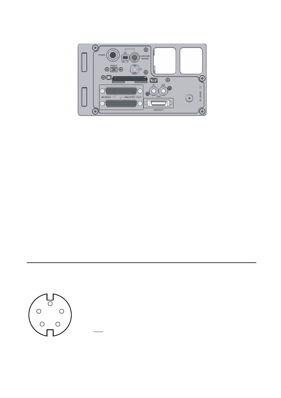
RIGHT SIDE PANEL CONNECTORS
• PHONES:
1/4" stereo jack / Main Monitor stereo output,
Sleeve = Gnd / Ring = Right / Tip = Left
• HEADSET:
Binder 5 pin male / Main Monitor stereo output (wired in parallel with PHONES,
and external Mic Input for Slate and communication
see wiring diagram below
• REMOTE :
USB-2 High speed / user interface remote control (future use)
• T.C.:
Lemo 5 pin male / Time Code input-output
see wiring diagram below
• AES OUT:
25pin Sub-D connector / AES-31 input & output (option in preparation)
see wiring diagram below
• SYNC IN:
SMA connector / Word Clock or Video sync input
• SYNC OUT:
SMA connector / Word Clock output
• ANALOGUE OUT: 25pin Sub-D connector / unbalanced direct out of channels 1 to 6 and balanced
output of Mix-L & Mix-R
see wiring diagram below
• ACCESSORY:
26pin 3M connector / AES input ( option ) and serial interface (future use)
compatible with SX-R4 and MINIR82 accessory connector
see wiring diagram below
HEADSET connector
Binder 5 pin Male Serie 711
SONOSAX ref: ……. or Binder nr 711 1 99 0095 102 05
Pin 1:
GND for Phone & Mic
Pin 2:
Phone Out Left
Pin 3:
Phone Out Right
Pin 4:
Comm. Mic High
Pin 5:
Comm Mic Low
Note: The switch located beside the 5 pin Binder connector
selects between 48V phantom and +6V for Electret microphone
for electrets microphone +6Vdc is on Pin 4
Solder side view
1
2
3
4
5