SONOSAX SX-62R Quick_Start User Manual
Page 31
SONOSAX SX62R
Quick Start Guide
Page 31 of 34
7.
ADDENDUM
7.1
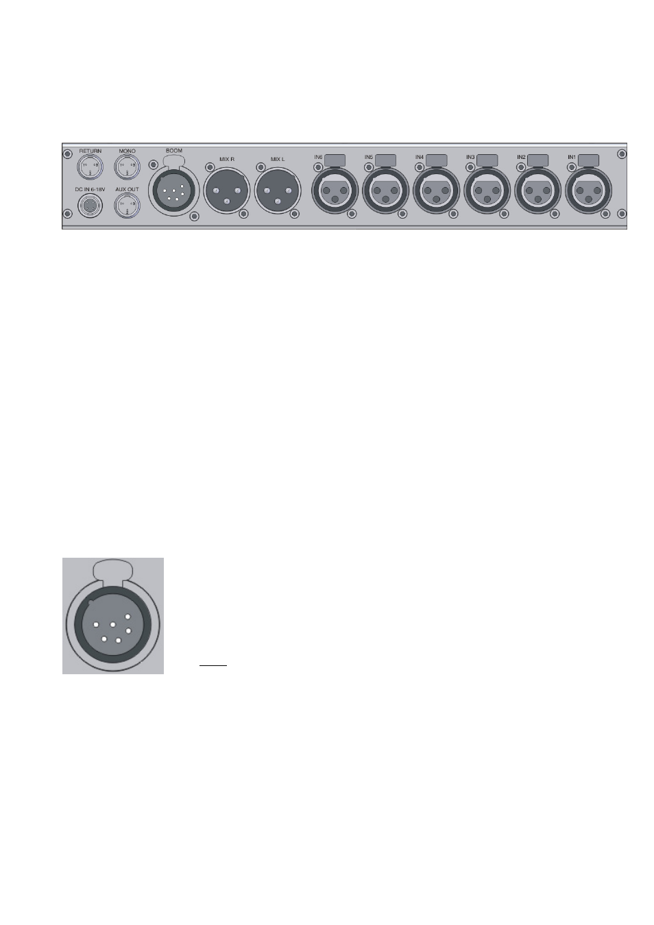
REAR PANEL CONNECTORS
• IN 1 to 6:
XLR3-F / Mic-Line Input / electronically balanced ( transformer less )
Pin 1 = Gnd / Pin 2 = Hi (+) / Pin 3 = Low (-)
• MIX-L MIX-R: XLR3-M / main output at line level / electronically balanced ( transformer less )
Pin 1 = Gnd / Pin 2 = Hi (+) / Pin 3 = Low (-)
• BOOM :
XLR6-F / MIC PL mic input with 48V & Secondary monitor output, stereo unbalanced
see wiring diagram below
• MONO:
TA3-M / main Mono output summing L & R / Line level unbalanced
Pin 1 = Gnd / Pin 2 = Hi (+) / Pin 3 = Gnd
• AUX OUT:
TA3-M / unbalanced stereo analogue output or digital AES out (menu AUX OUT)
Pin 1 = Gnd / Pin 2 = Left / Pin 3 = Right
• RETURN:
TA3-M / unbalanced stereo analogue line input (for monitoring or additional feed)
Pin 1 = Gnd / Pin 2 = Left / Pin 3 = Right
• DC IN 6-18V: Hirose 4pin-F / external DC power supply
Pin 1 = 0VDC or Gnd / Pin 2 = n.c / Pin 3 = n.c / Pin 4 = +VDC 6 to 18V
Wiring diagrams for BOOM connector
XLR-6F
Compatible with SONOSAX BOOM BOX
mating cable connector:
XLR-6M
Pin 1 =
Left output secondary Monitor
Pin 2 =
Right output secondary Monitor
Pin 3 =
Gnd secondary Monitor out
Pin 4 =
PL microphone Hi +
Pin 5 =
PL microphone Lo -
Pin 6 =
PL microphone Gnd & CALL
NOTE:
Bridge Pin 6 ( Mic Gnd) and pin 3 ( Monitor Gnd ) via a switch to activate
the PL duplex communication ( Boom Call )