Smithco Spray Star 3000 (sn 3500 – Current) Parts & Service Manual User Manual
Page 92
90
Accessories
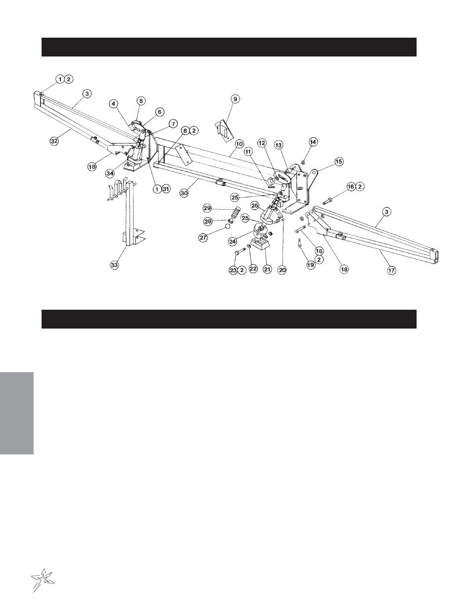
14-100 BOOM DRAWING
14-100 BOOM INSTALLATION INSTRUCTIONS
1. Lay out all parts in an orderly manner.
2. Attach the Boom frame to the two vertical posts at the rear of the Spray Star vehicle using four (Ref# 9)
Boom brackets on the mounting posts. DO NOT tighten the large clamps at this point.
If nozzle bodies are factory installed, attach the right outer boom and hinge assembly and the left outer
boom and hinge assembly to the center boom assembly using items in boom drawing, (Ref# 19) Bolts
and (Ref# 4) Knobs. Tighten the bolts securely and knob loosely. Level the outer right and left boom
sections with the center section. Tighten the (Ref# 4) Knobs. Nozzles on the outer boom assemblies are
to be towards the rear and match the position of the nozzles on the center boom.
3. If nozzle bodies are not installed go to the plumbing and nozzle kit page for your type of nozzle kit
4. Connect the three
3
/
4
" orange supply hose which comes from the electric boom control valve, to the
3
/
4
"
hose barb inlet in the steel tees on each boom section. Take care to insure the right-center-left boom
sections are correctly connected to the supply hoses from the right-center-left control valves. Secure with
hose clamp.
Both the 16-806 and the 16-807 nozzle kits are furnished with average size nozzles. The user should never hesi-
tate to change nozzle sizes to achieve the desired spray application rate. See nozzle charts included.
The nozzles in both the 16-806 and the 16-807 nozzle kits may be replaced with Spraying Systems Co.
“FULLJET” and “FLOODJET” nozzles. Consult Spraying Systems Co. catalog for more information.