Adjustments – Smithco Spray Star 3000 (sn 3500 – Current) Parts & Service Manual User Manual
Page 10
8
Ser
vice
ADJUSTMENTS
FACET CARBURETOR
The idle speed adjustment screw, and the idle fuel mixture adjustment needle are accessible on the exterior of
the carburetor. There are three factors that control the conversion of the fuel and mixture into engine power.
These factors are engine compression, ignition and correct carburetor adjustment. Correct carburetor adjust-
ment cannot be obtained unless engine compression and ignition meet specifications.
To make the adjustments, start the engine and operate it until it has reached normal operating temperature. Be
sure the choke and throttle controls are pushed all the way in.
Start the adjustments by setting the idle speed screw to obtain an engine speed of 750 RPM. Then turn idle fuel
mixture adjustment needle in (clockwise) until the engine begins to roll. Then, back it out slowly until the engine
is running smoothly. Reset the idle speed to 750 RPM.
VALVE CLEARANCE
The valve clearance can also be adjusted without the engine running. Rotate the crankshaft until #1 cylinder is at
the top of the compression stroke. Check the timing marks. It should read 0 or TDC. Both valves on #1 cylinder
are now closed. Set the valve clearance on both valves (Intake Lash Cold 0.22 mm, Exhaust Lash Cold 0.32
mm, Next, Rotate the crankshaft 180° and set the valve lash on both valves on #2 cylinder. Again rotate the
crankshaft 180° and set the valve lash on both valves on #4 cylinder. Rotate the crankshaft another 180° and
set the valve lash on both valves on #3 cylinder.
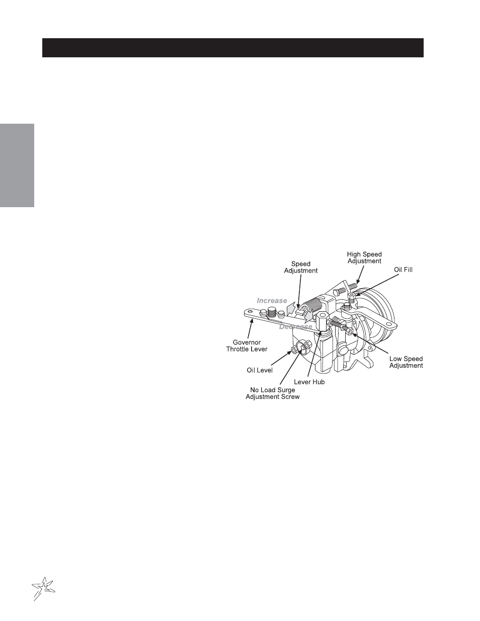
GOVERNOR
Before making any governor adjustments, check the governor drive
belt tension with a belt tension gauge. Set the belt to 75 lb (34 kg)
new, 50 lb (23 kg) used. (Replace the belt if cracked or damaged
during shipping, etc.).
The first adjustment is the governor-to-carburetor control
rod adjustment. With the control rod connected, manu-
ally move the governor throttle lever to the maximum
open throttle position. Check that the carburetor
throttle shaft lever is set from
1
/
32
to
1
/
4
of an inch
from its maximum opening position stop. If neces-
sary, adjust length of the control rod to obtain the
setting.
To perform a high-speed adjustment, attach a tachometer
to the engine, then run the engine until it reaches normal
operating temperature.
1. Loosen the lock nut on the high speed stop screw.
2. Disengage engine load.
3. Slowly pull the throttle control to desired maximum no load engine speed.
4. Adjust the high speed stop screw on the governor to attain the desired maximum engine speed. Do NOT
exceed the recommended maximum RPM.
5. Tighten the lock nut.
The next adjustment is for speed. Proper governor operation requires a difference between full-load and no-load
governor speed. Too small an RPM spread between the two speeds will cause governor hunting and surging. Too
large a spread will cause the low response. For this governor, normal RPM spread is approximately 250 RPM
within the full load speed range of 2000-2800 RPM. If the engine hunts at maximum speed, no-load condition,
turn the surge screw clockwise into governor until hunting just stops and tighten locknut. Do not turn screw in far
enough to increase engine speed.