Maintenance – Smithco Spray Star 1000 (sn 100489 – 100523) Parts & Service Manual User Manual
Page 6
4
Ser
vice
MAINTENANCE
Before servicing or making adjustments to machine, stop engine and remove key from
ignition.
Use all procedures and parts prescribed by the manufacturer's. Read the engine manual
before operation.
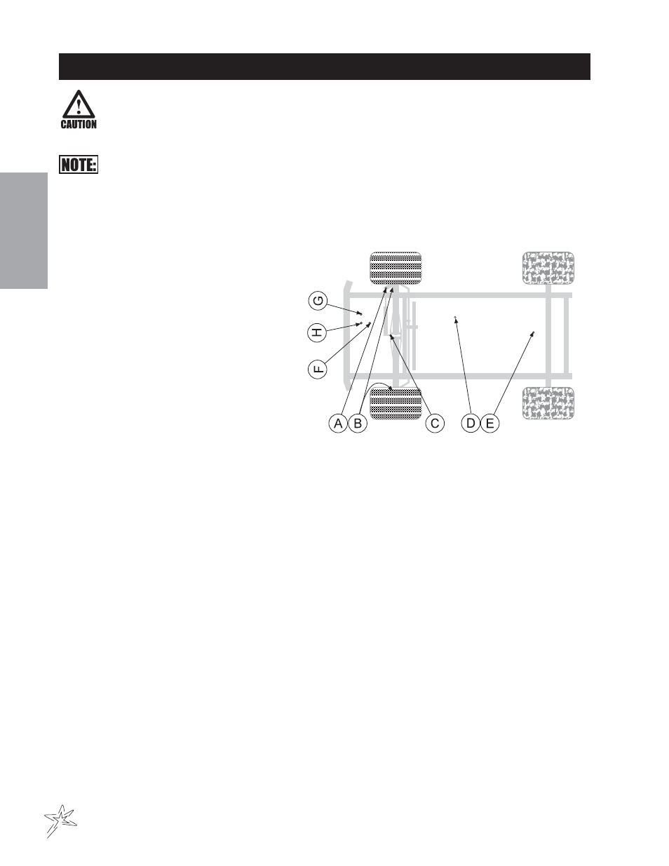
LUBRICATION
Use No. 2 General purpose lithium base grease and lubricate every 100 hours. The Spray Star 1000 has 9
grease fittings.
A. One on the rod end of hydraulic cylinder.
B. One on each the right and left spindles.
C. One on the center front pivot.
D. One on the pump pivot.
E. One on the brake relay.
F. One on the pedal relay.
G. One on the reverse pedal.
H. One on the forward pedal.
Every 500 hours of operation, separate the hy-
drostatic pump and the engine, clean the splined
areas and lightly grease the male portion of the
pump spline. Use either Dow Corning® G-N
Metal Assembly Paste or #77 Assembly Paste
(Kohler# 25 357 12-s).
As you mount the pump back onto the engine, be certain the mating surfaces are clean and free of any foreign
material and that the pump is correctly aligned.
ELECTRICAL CONNECTIONS
Use dielectric grease on all electrical connections.
FLOW METER MAINTENANCE AND ADJUSTMENT (440 SYSTEM ONLY)
1. Remove Flowmeter from Sprayer, brush away any debris and flush with clean water to remove any
foreign material.
2. Remove the retaining rings carefully. Remove the bearing hub, turbine hub, and turbine from inside
flowmeter.
3. Clean the turbine and hubs of metal filings and any other foreign material. Use pressurized air to blow
metal filings and debris out of both hub and turbine. Check blades for wear. Holding turbine and bearing
in your hand, spin turbine. It should spin freely with very little drag.
4. If bearing hub stud is adjusted or replaced, verify the turbine fit before reassembling. Put turbine hub and
retaining ring in place. Put bearing hub with turbine against turbine hub inside the flowmeter housing.
Put the retaining ring into the groove, to lock bearing hub in place. Spin turbine by blowing on it. Tighten
bearing hub stud until turbine stalls. Loosen the stud 1/3 turn. The turbine should spin freely.
5. Use a low pressure (5PSU) jet of air through flowmeter in the direction of flow and again in opposite
direction to verify that the turbine spins freely. If there is drag, loosen the stud on the bearing hub 1/16
turn until the turbine spins freely.
6. If turbine spins freely and the cables have been checked, but the flowmeter is not totalizing properly,
verify that the sensor assembly is threaded all the way into the flowmeter body and the orientation
groove on top of the sensor is parallel with the flowmeter body. If flowmeter still does not totalize, replace
sensor assembly.
- Spray Star 1008 Parts & Service Manual Spray Star 1000 (sn 100459 – 100488) Parts & Service Manual Spray Star 1000 (sn 100413 – 100443) Parts & Service Manual Spray Star 1000 (sn 100444 – 100458) Parts & Service Manual Spray Star 1000 (sn 100524 – 100548) Parts & Service Manual Spray Star 1000 (sn 100549 – Current) Parts & Service Manual Spray Star 1011 Parts & Service Manual