Installation instructions – SL Power Electronics GPMP600 User Manual
Page 2
WARNING! SHOCK HAZARD! Dangerous voltages are present on some components, printed wiring traces and heatsinks.
AIRFLOW/COOLING: The GPHP600/700 series is designed with two integral fans that are rated 54 cfm total.
VOLTAGE ADJUSTMENT: Factory set to specified voltage. User accessible pot allows adjustment over a range of ±5%
of nominal voltage. The potentiometer is located on the A2 PWB located behind and above J1.
Connector: ERNI Type H15 P/N 123767 or AVX ELCO 108456015001169 DIN 41612 Style H15
AC INPUT
STATUS and CONTROL
Line
Z32
AC Power Fail
D22
Neutral
D30
DC Power Good
Z20
Reference to Common
Ground
Z28, D26
Inhibit
Z24
DC OUTPUT
Z12, D14, Z16, D18
Main Output
Output #1
Z4, D6, Z8, D10
Rtn (Common)
Condor DC Power Supplies Inc. will not be liable for the safety, reliability or performance of these power supplies if a) any changes,
modifications or repairs are carried out by other than authorized agents of Condor DC Power Supplies Inc., or b) the installation of the supply
is not in accordance with these installation instructions and the applicable UL, CSA, and EN/IEC safety standards.
41-35343-0002A 8/5/04
INSTALLATION INSTRUCTIONS
GPMP600/700 SERIES (Contd.)
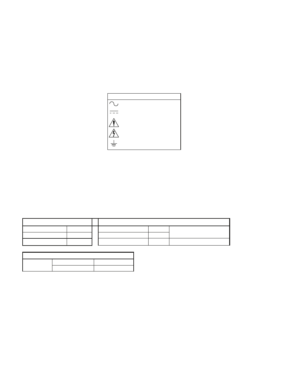
Attention, Consult
Accompanying Documents
Alternating Current
Attention, Dangerous Voltages
Earth (Ground)
EXPLANATION OF SYMBOLS
Direct Current
VOLTAGE ADJUSTMENT: Factory set to specified voltage. User
accessible pot allows adjustment over a range of ±5% of nominal voltage.
The potentiometer is located on the A2 PWB located behind and above J1.
C O N N E C T I O N S