SL Power Electronics G2T60 User Manual
Page 2
ISOLATION: The creepage distance between primary and secondary circuits is 8 mm minimum. The
required creepage and clearance distances from primary circuits to secondary circuits must be
maintained after installation to preserve the intended safety.
TEMPERATURES: The maximum operating temperatures of certain safety components, as defined in
the applicable safety standards, must not be exceeded after installation to preserve the intended safety.
The output power, ambient air temperature and the availability, amount, direction and/or restriction of
airflow influence the temperatures of these components.
OVERCURRENT PROTECTION: Fuses for both Line and Neutral are provided in the power supply.
NOTE: For use in permanently installed equipment, remove Fuse F2 and replace with a jumper wire.
WARNING! RISK OF FIRE! A blown internal fuse is an indication of catastrophic failure of circuit
component(s). Refer to fuse marking on the power supply for rating. Repair must be performed by
SLPE authorized personnel.
WARNING! SHOCK HAZARD! Dangerous voltages are present on some components, printed wiring
traces and heatsinks.
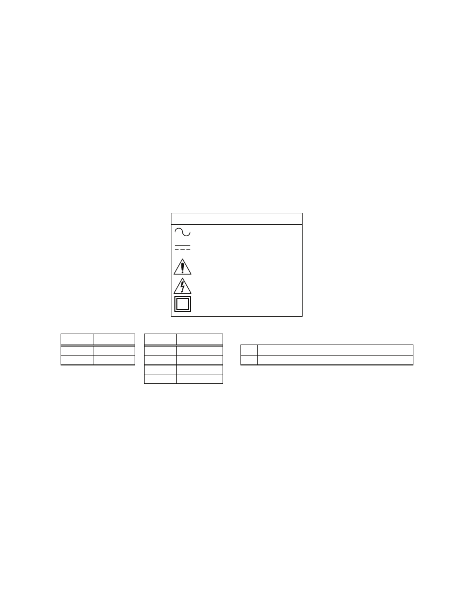
Attention, Consult
Accompanying Documents
Alternating Current
Attention, Dangerous Voltages
Class II Equipment
EXPLANATION OF SYMBOLS
Direct Current
C O N N E C T I O N S
J1 Pin
AC Input
J2 Pin
DC Output
MATING CONNECTORS
1
Line
1
Output (+)
J1
Amp Housing 640250-3 Contact 770476-1
3
Neutral
2
Output (+)
J2
Amp Housing 640250-4 Contact 770476-1
3
Return
4
Return
SLPE will not be liable for the safety, reliability or performance of these power supplies if a) any changes, modifications or repairs are carried out by other than authorized agents of
SLPE, or b) the installation of the supply is not in accordance with these installation instructions and the applicable UL, CSA, EN, and IEC safety standards.
41-35510-0002 Rev. D 08/18/2008
Page 2 of 2