Gld150 series installation instructions – SL Power Electronics GLD150 User Manual
Page 2
GLD150 SERIES INSTALLATION INSTRUCTIONS
TEMPERATURES: The maximum operating temperatures of certain safety components, as defined in
the applicable safety standards, must not be exceeded after installation to preserve the intended safety.
The output power, ambient air temperature and the availability, amount, direction and/or restriction of
airflow influence the temperatures of these components.
FUSING: Fuses for both Line and Neutral are provided in the power supply. A blown fuse is an
indication of catastrophic failure of circuit component(s). Repair must be performed by Condor
authorized personnel. Refer to fuse markings for type and rating.
WARNING! SHOCK HAZARD! Dangerous voltages are present on some components, printed wiring
traces and heatsinks.
CONNECTIONS
J1 AC Input
J2 Signal Out
J3 DC Output
FAN
MATING CONNECTORS
1 Earth
1 Inhibit
1 Return
1 12 V (-)
J1: Molex P/N 39-01-4051 (Housing)
3 AC Neutral
2 + Sense
2 Return
2 12 V (+)
Molex P/N 39-00-0038 (Pins)
5 AC Line
3 Power Good 3 Output (+)
J2 and FAN: Amp MTA-100 Receptacle
4 - Sense
4 Output (+)
J3: Molex P/N 39-01-2080 (Housing)
5 Common
5 Return
Molex P/N 39-00-0182 (Pins)
6 Power Fail
6 Return
7 Output (+)
CAUTION: Do not exceed 7 Amps per pin on connector J3
8 Output (+)
SL Power Electronics, Corp. will not be liable for the safety, reliability or performance of these power supplies if a) any changes, modifications or repairs are carried out by other
than authorized agents of SL Power Electronics, Corp., or b) the installation of the supply is not in accordance with these installation instructions and the applicable UL, CSA, and
EN/IEC safety standards.
41-34865-0001 Rev. E 12/14/06
Page 2 of 2
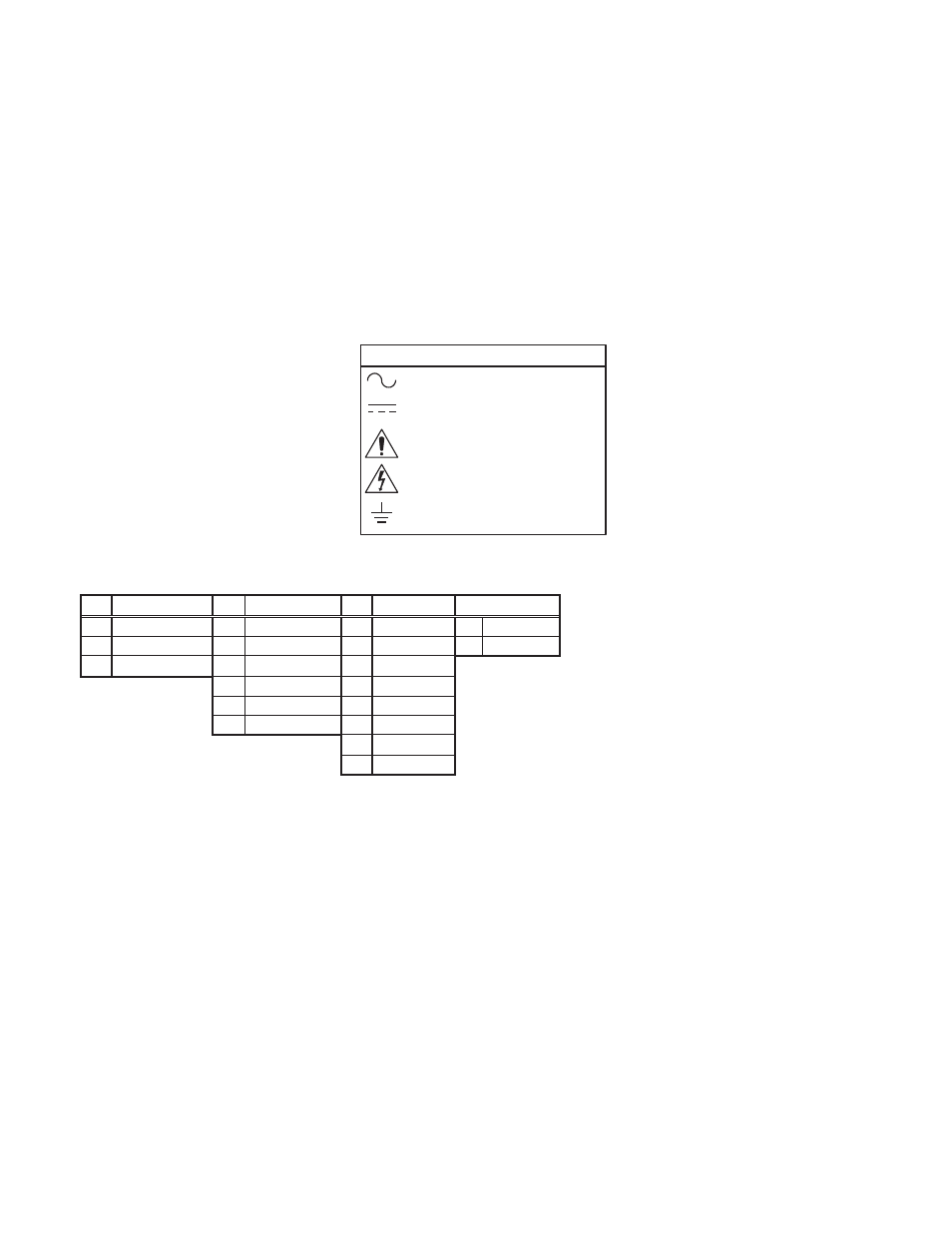
Attention, Consult
Accompanying Documents
Alternating Current
Attention, Dangerous Voltages
Earth (Ground)
EXPLANATION OF SYMBOLS
Direct Current