Gld140 series installation instructions – SL Power Electronics GLD140 User Manual
Page 2
GLD140 SERIES INSTALLATION INSTRUCTIONS
OVERVOLTAGE PROTECTION: The output is monitored for an overvoltage condition. In some applications where an
overvoltage condition could result in a hazard as defined in applicable safety standards, redundant or additional overvoltage
protection may be required. Consult factory for details.
CAUTION: When performing Dielectric Strength Tests, catastrophic failure of the unit may result if a Dielectric Strength
test voltage greater than 1800 V ac is applied between primary and secondary circuits. The components providing isolation
from primary to secondary cannot be tested while installed in the power supply without overstressing basic (primary to
ground) insulation. All isolating components are individually 100 % tested at 4800 V ac prior to installation.
TEMPERATURES: The maximum operating temperatures of certain safety components, as defined in the applicable safety
standards, must not be exceeded after installation to preserve the intended safety. The output power, ambient air temperature
and the availability, amount, direction and/or restriction of airflow influence the temperatures of these components.
FUSING: Fuses for both Line and Neutral are provided in the power supply. A blown fuse is an indication of catastrophic
failure of circuit component(s). Repair must be performed by Condor authorized personnel. Refer to fuse markings for type
and rating.
WARNING! SHOCK HAZARD! Dangerous voltages are present on some components, printed wiring traces and heatsinks.
CONNECTIONS
J1 AC Input
J2 Signal Out
J3
DC Output
J5 FAN
1 Earth
1 + Sense
9, 10, 19, 20
V1
1
Fan Return
3 AC Neutral
2 - Sense
5, 14, 15
V2
2
+ Fan
5 AC Line
3 Power Fail
4
V2 Sense
4 Power Good
1
V3
MATING CONNECTORS
5 Common
11
V3 Return
J1: Molex P/N 39-01-4051 (Housing)
6 Inhibit
2
V4
Molex P/N 39-00-0038 (Pins)
3, 6-8, 12, 13, 16-18 Common
J2 and FAN: Amp MTA-100 Receptacle
J3: Molex P/N 39-01-2200 (Housing)
Molex P/N 39-00-0038 (Pins)
CAUTION: Do not exceed 7 A per pin on connector J3
Condor DC Power Supplies Inc. will not be liable for the safety, reliability or performance of these power supplies if a) any changes, modifications or repairs are carried out by other
than authorized agents of Condor DC Power Supplies Inc., or b) the installation of the supply is not in accordance with these installation instructions and the applicable UL, CSA,
and EN/IEC safety standards.
41-34338-0001 Rev. G 11/30/05
Page 2 of 2
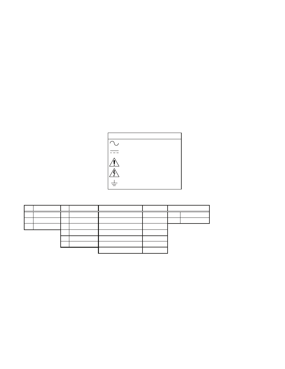
Attention, Consult
Accompanying Documents
Alternating Current
Attention, Dangerous Voltages
Earth (Ground)
EXPLANATION OF SYMBOLS
Direct Current
- GPC55 GPC40 GECA20 GLC65 Single GLC65 Triple Output GLM65 Triple Output GEM600 GEM750 MINT1022 GLM65 Single Output GLD150 GPFC110 GLM75 Single Output GLM50 Triple O/P GPFM250 GPMP600 GPMP700 GSM28 GSM15 G2T60 GPC200 GPC130 GPC140 GLC75 Multiple Output GNT400 GNT30 GLC50 Single GLC50 Triple GPFM115 GPFM600 GPM55