Contd.) – SL Power Electronics GEM600 User Manual
Page 2
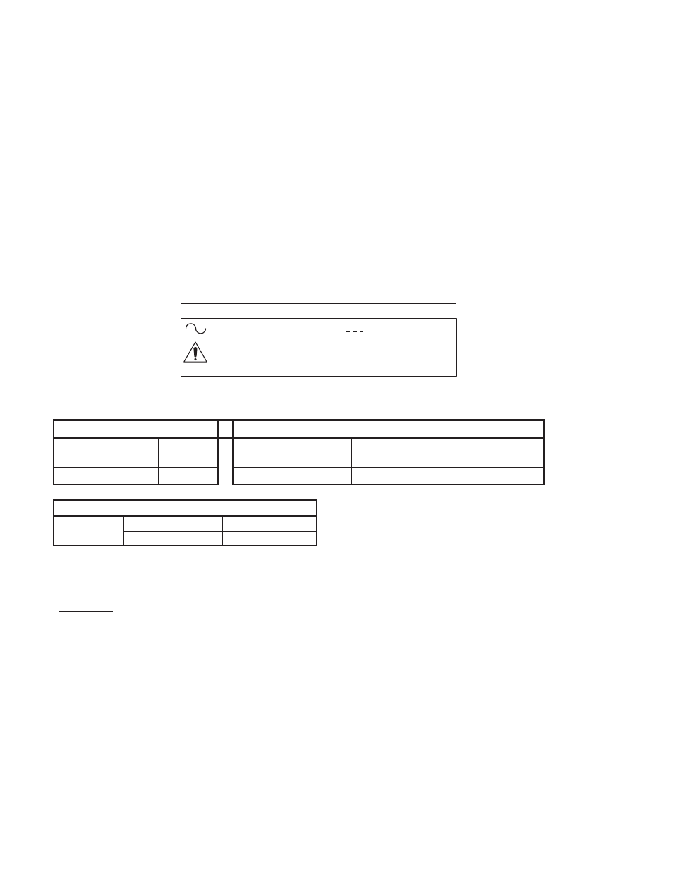
EXPLANATION OF SYMBOLS
Direct Current
Attention, Consult
Accompanying Documents
Alternating Current
GEM600/750 SERIES
INSTALLATION INSTRUCTIONS
(Contd.)
CURRENT SHARING: The Optional Built-in OR-ing diode allows multiple units to share the load.
NOTE: Adjacent units must be set within 0.2% of each other for proper current share.
VOLTAGE ADJUSTMENT: Factory set to specified voltage. User accessible pot allows adjustment over a range of ±5%
of nominal voltage. The potentiometer is located on the A2 PWB located behind and above TB3.
SPACINGS: The required creepage and clearance distances from primary circuits to ground and secondary circuits must be
maintained after installation to preserve the intended safety.
WARNING! RISK OF FIRE! A blown internal fuse is an indication of catastrophic failure of circuit component(s). Repair
must be performed by SL Power Electronics authorized personnel.
AIRFLOW/COOLING: The GEM600/700 series is designed with an integral fan rated 42 CFM.
C O N N E C T I O N S
AC INPUT – TB1
STATUS and CONTROL – J4 (AMP P/N 640456-4)
Line
1
Power Good
1
Neutral
2
Power Fail
2
Reference to Common
Ground
3
Inhibit
4
DC OUTPUT – TB2 and TB3
TB2 Pins 1-3
Main Output
Output
TB3 Pins 1-3
Rtn (Common)
OPTIONS:
A – Terminal Block (EBY P/N 6002-03-N-01) (Cooper Magnum A214203)
B – Bussbars
T – Phoenix Contact (P/N 1732034)
D - N+1 OR-ing Diode. Will allow 2 or more power supplies to be connected in parallel and share the output
load.
SL Power Electronics, Corp. (SLPE) will not be liable for the safety, reliability or performance of these power supplies if a) any changes, modifications or repairs are
carried out by other than authorized agents of SLPE., or b) the installation of the supply is not in accordance with these installation instructions and the applicable
UL, CSA, and EN/IEC safety standards.
41-35627-0001, Rev A 4/5/07