2 analog signal outputs – j4, Table 2: pin-out of serial comm connector j5, Table 3: serial communications connections – Delta Faucet NANOTRACE DF-745 User Manual
Page 36
32 DF-745
Connecting to External Devices
A program to facilitate serial communications is available from Delta F.
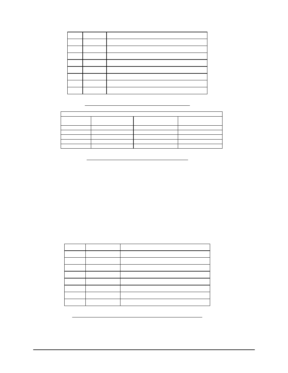
Pin #
Signal
Description
J5-8
GND
Ground
J5-7
TX-
4 wired 485 paired with TX+
J5-6
Key
Unused
J5-5
RX-
4 wire 485 paired with RX+
J5-4
Unused
J5-3
Unused
J5-2
TX+
Data transmitted by the analyzer via RS-232 or RS-485
J5-1
RX+
Data received by the analyzer via RS-232 or RS-485
Table 2: Pin-out of Serial Comm Connector J5
Pin assignments
DF-760/750
PC-DB9/RS-232
PC-DB25/RS-232
PC/RS-485
converter
1: RX+
3: TD
2: TD
TX+
2: TX+
2: RD
3: RD
RX+
8: Gnd
5: Gnd
7: Gnd
5: RX-
TX-
7: TX-
RX-
Table 3: Serial Communications Connections
6.2 Analog Signal Outputs – J4
The analog voltage output correlating to the front panel display reading is provided on the
rear of the analyzer through connector J4. The full scale voltage is set at the factory at the
time of order to: 0 to 1 VDC, 0 to 2 VDC, 0 to 5 VDC, or 0 to 10 VDC. The output is
electrically isolated from all other analyzer outputs, and from chassis (Earth) ground. See
page 55 for additional information on setting the Analog Output. The output may be tested
with the use of the analog voltage test routine found on page 59.
6.3 4-20 mA Outputs – J4
J4 Pin #
Moisture Signal
Description
J4-8
GND
Ground
J4-7
Key
J4-6
A Out +
Analog Voltage Output (+)
J4-5
A Out -
Analog Voltage Output (-)
J4-4
Unused
J4-3
Unused
J4-2
4-20 mA +
4-20 mA Output (+)
J4-1
4-20 mA -
4-20 mA Output (-)
Table 4: Pin-Out of Moisture Signal Output Connector J4